Inkjet recording device

Inactive Publication Date: 2012-03-22
SEIKO EPSON CORP
View PDF24 Cites 12 Cited by
  • Summary
  • Abstract
  • Description
  • Claims
  • Application Information

AI Technical Summary

Benefits of technology

[0032]According to this configuration, it is possible to re

Problems solved by technology

A problem encountered with an upward-facing access face is that particles and ink mist tend to become deposited on the access face from above, giving rise to defects of the ink fixation part.
Specifically, damage to the recording medium by

Method used


Image

  • Inkjet recording device
  • Inkjet recording device
  • Inkjet recording device

Examples


Example

First Modification Example

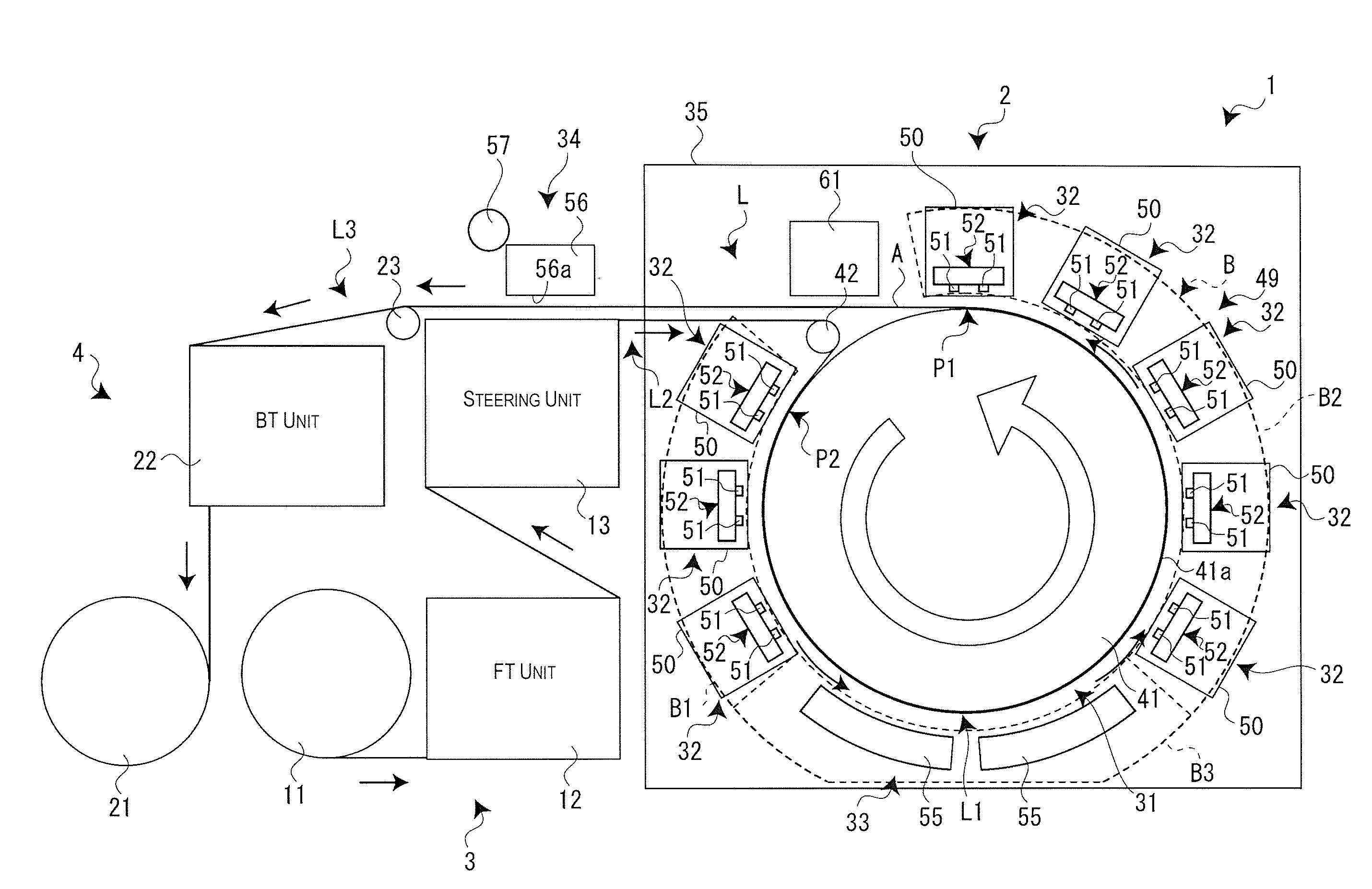
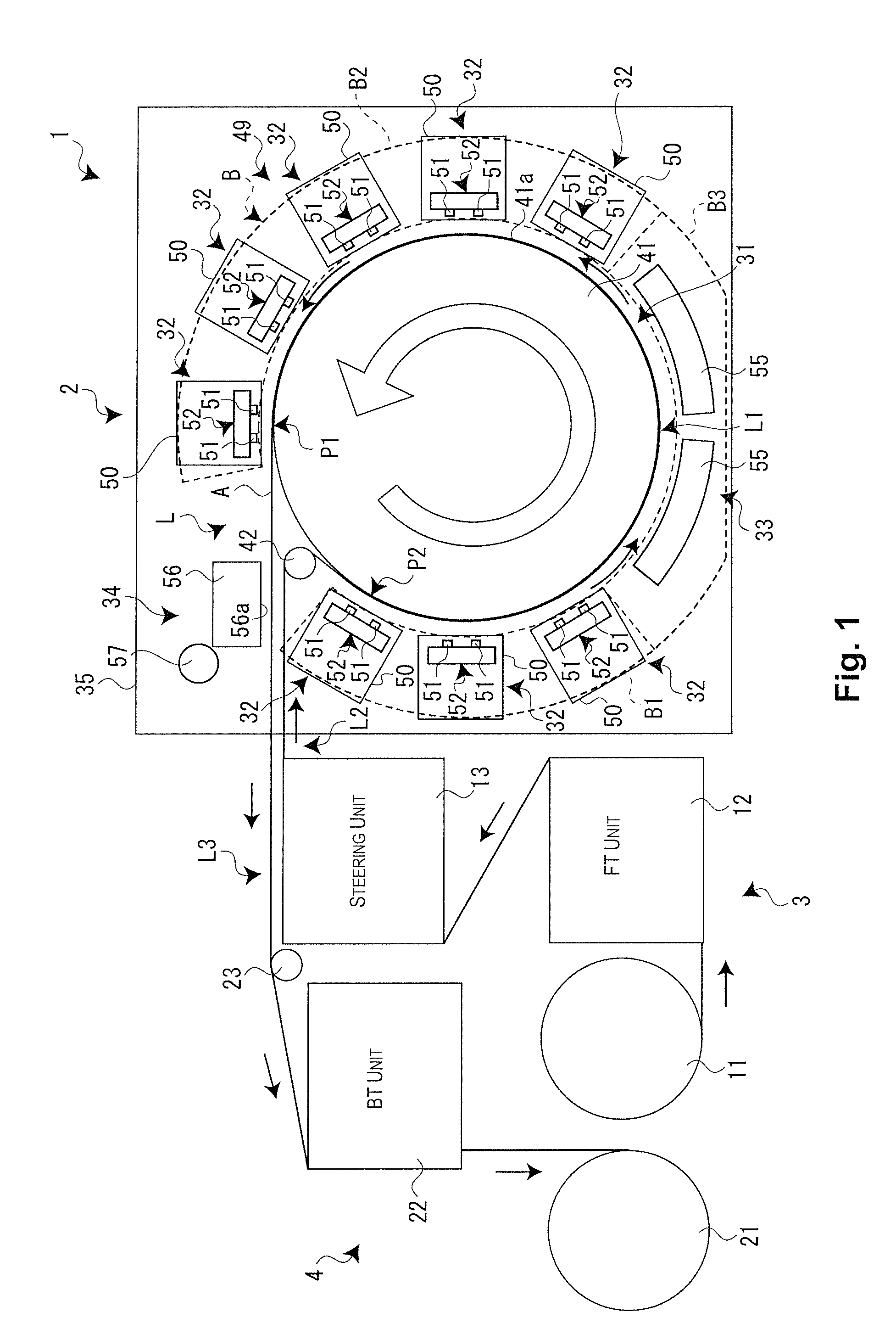
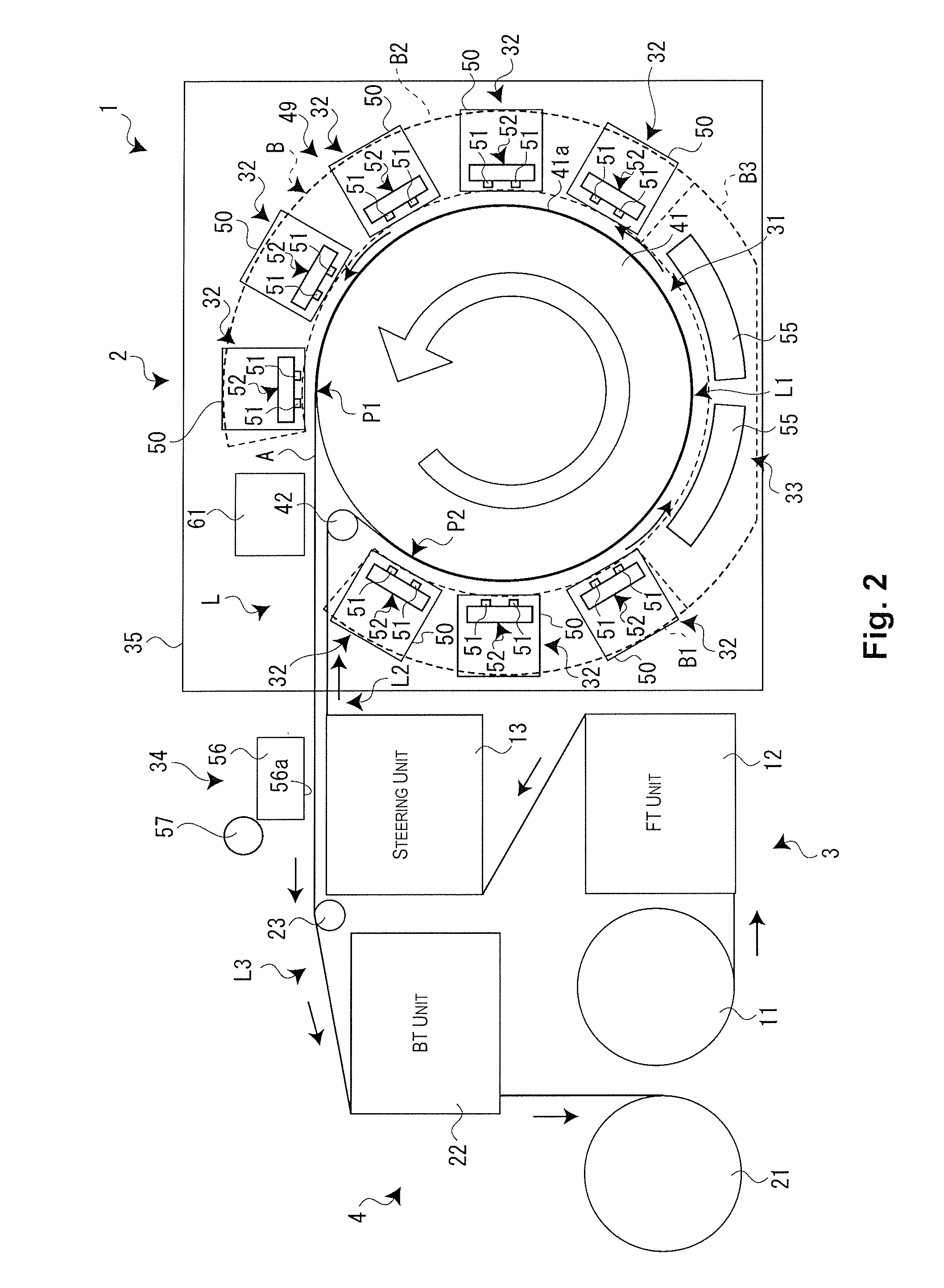
[0069]Also, whereas the aforedescribed embodiment configuration was one in which the main curing unit 34 is arranged facing the upstream end part of the recovery feed path L3, a configuration like that depicted in FIG. 2, in which a coating device 61 for coating a coating agent onto the recording medium A is arranged at this location, and the main curing unit 34 is arranged at a downstream position thereof, is also acceptable. In this case, the printed recording medium A can be coated over its entire surface by a simple configuration. The coating device 61 may be one of spray coater design, or one of roll coater design. Of course, one of inkjet design is also acceptable.

Example

Second Modification Example

[0070]Further, whereas the aforedescribed embodiment configuration was one in which the recording medium A is outfed in the horizontal direction from the uppermost end by the outfeed roller 23, and the recording medium A is infed at an infeed position P2 in proximity to the outfeed position P1, such a configuration is not given by way of limitation, provided that the configuration is one of outfeed in a tangential direction from the upper half part of the rotating drum 41. For example, as depicted in FIG. 3, a configuration in which the outfeed position P1 is at the diagonal upper right part, the recording medium A is outfed in a tangential direction (downward diagonally to the right) from that outfeed position P1, and the recording medium A is infed to the infeed position P2 in the diagonal lower left part is also acceptable.

[0071]Still further, whereas in the aforedescribed embodiment, the printing process was carried out using ultraviolet-curing ink, an...


PUM


Abstract

An inkjet recording device includes: a medium feed part including a rotating body that rotates about a horizontal axis to feed an elongated recording medium while the recording medium is in contact against a circular outer face of the rotating body so that the recording medium is fed along an arcuate feed path conforming to the outer face; a medium recording part having a plurality of recording units arranged along the feed path, and that carries out recording through ejection deposition of ink onto the recording medium; an outfeed part that outfeeds the recording medium in a tangential direction from the rotating body at an outfeed position positioned in an upper half of the rotating body; and an ink fixation part facing from above the recording medium outfed from the rotating body, and fixes the ink that has been ejection-deposited onto the recording medium by the medium recording part.

Description

CROSS-REFERENCE TO RELATED APPLICATIONS[0001]This application claims priority to Japanese Patent Application No. 2010-212098 filed on Sep. 22, 2010. The entire disclosure of Japanese Patent Application No. 2010-212098 is hereby incorporated herein by reference.BACKGROUND[0002]1. Technical Field[0003]The present invention relates to an inkjet recording device for carrying out a recording process on an elongated recording medium, such as paper or film, which is fed by making the medium conform about a rotating body.[0004]2. Related Art[0005]There is known in the art, in the field of inkjet recording devices, a device provided with a conveyor drum that rotates about a horizontal axis and conveys an elongated recording medium wound about its outside face, a plurality of printing sections of inkjet format disposed along the outside face of the conveyor drum, an infeed roller at the bottom of the conveyor drum, for infeeding the recording medium to the conveyor drum, and an outfeed roller...

Claims


Application Information

Patent Timeline
IPC IPC(8): B41J2/01
CPCB41J13/223B41J11/002B41J11/00214
Inventor WANIBE, AKIHISA
Owner SEIKO EPSON CORP
Why Eureka
Try Eureka