Image display apparatus and image display system

a technology of image display and display apparatus, applied in the field of image display apparatus and image display system, can solve the problem of brightness unevenness of visually recognized images, and achieve the effect of more reliably suppressing the brightness unevenness of images visually recognized through shutter glasses

Active Publication Date: 2012-03-22
SEIKO EPSON CORP
View PDF7 Cites 4 Cited by
  • Summary
  • Abstract
  • Description
  • Claims
  • Application Information

AI Technical Summary

Benefits of technology

[0028]As a result, any change in transmittance of the shutter glasses during the light blocking to transmitting transition period and the light transmitting to blocking transition period can be canceled by adjusting the light source light level, whereby brightness unevenness of an image visually recognized through the shutter glasses can be more reliably suppressed.

Problems solved by technology

That is, the visually recognized image suffers from brightness unevenness.

Method used


Image

  • Image display apparatus and image display system
  • Image display apparatus and image display system
  • Image display apparatus and image display system

Examples


first embodiment

[0037]A first embodiment of the invention will be described below with reference to the drawings.

Configuration of Image Display System

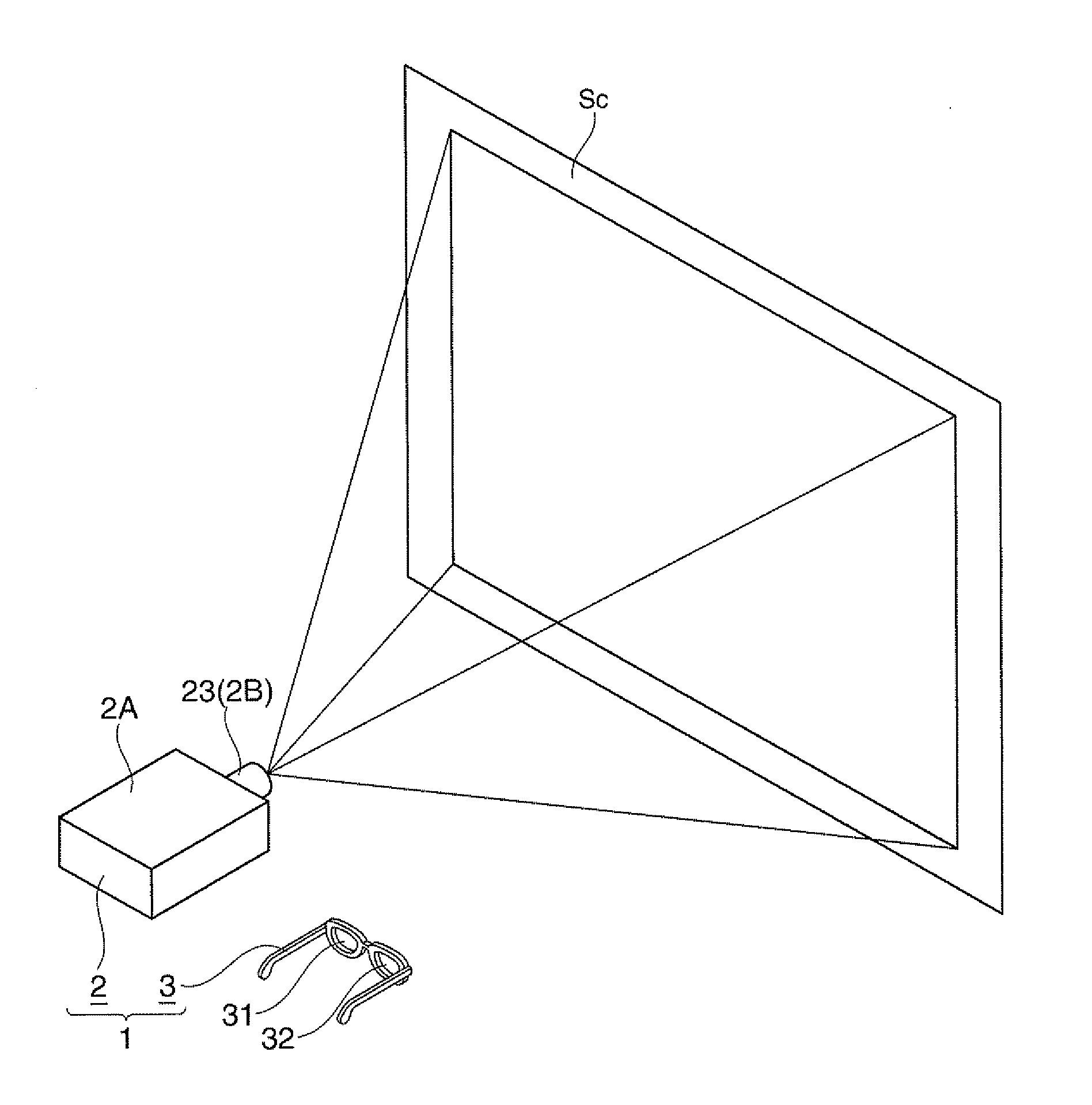
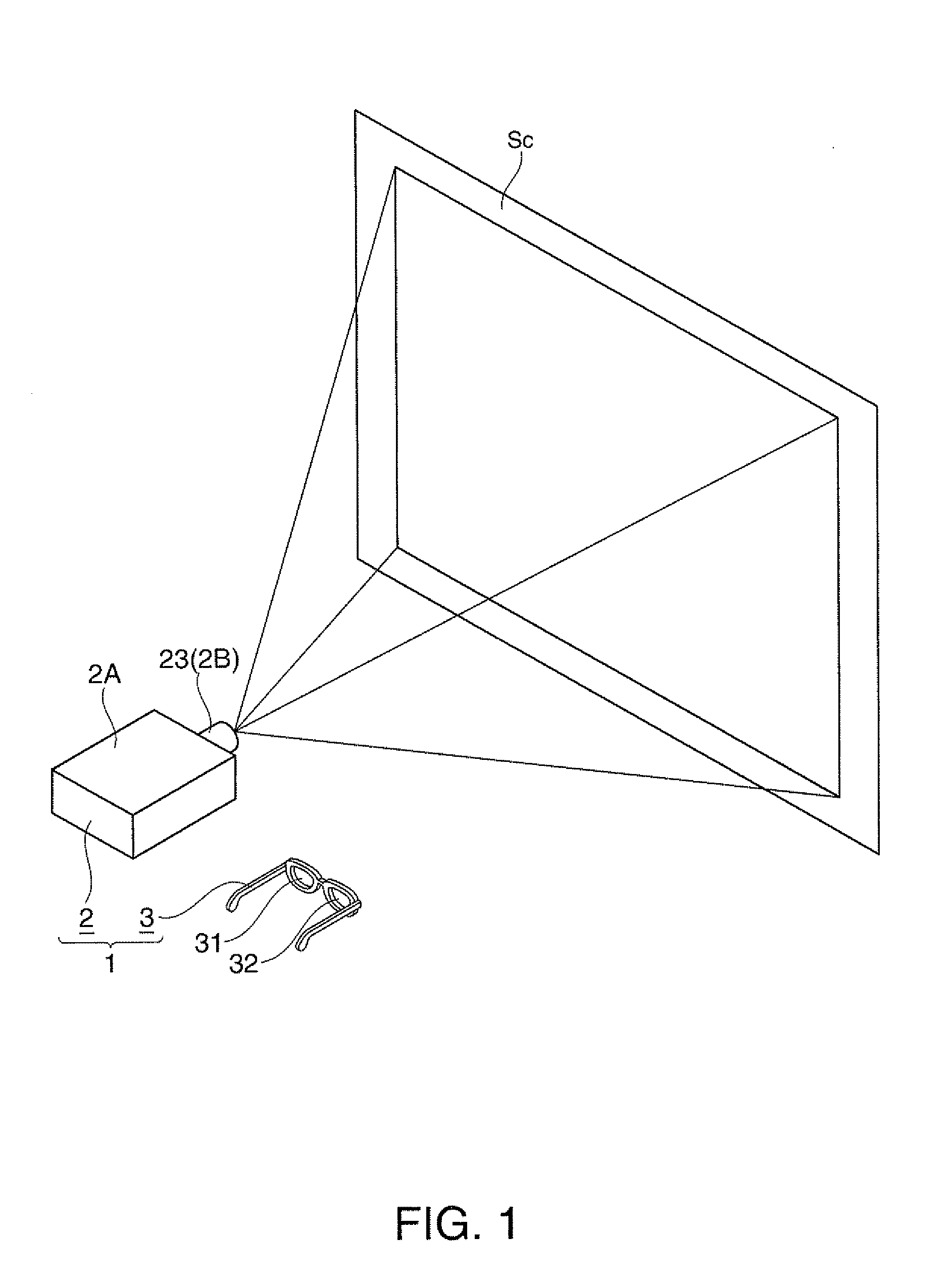
[0038]FIG. 1 is a perspective view showing how to use an image display system 1.

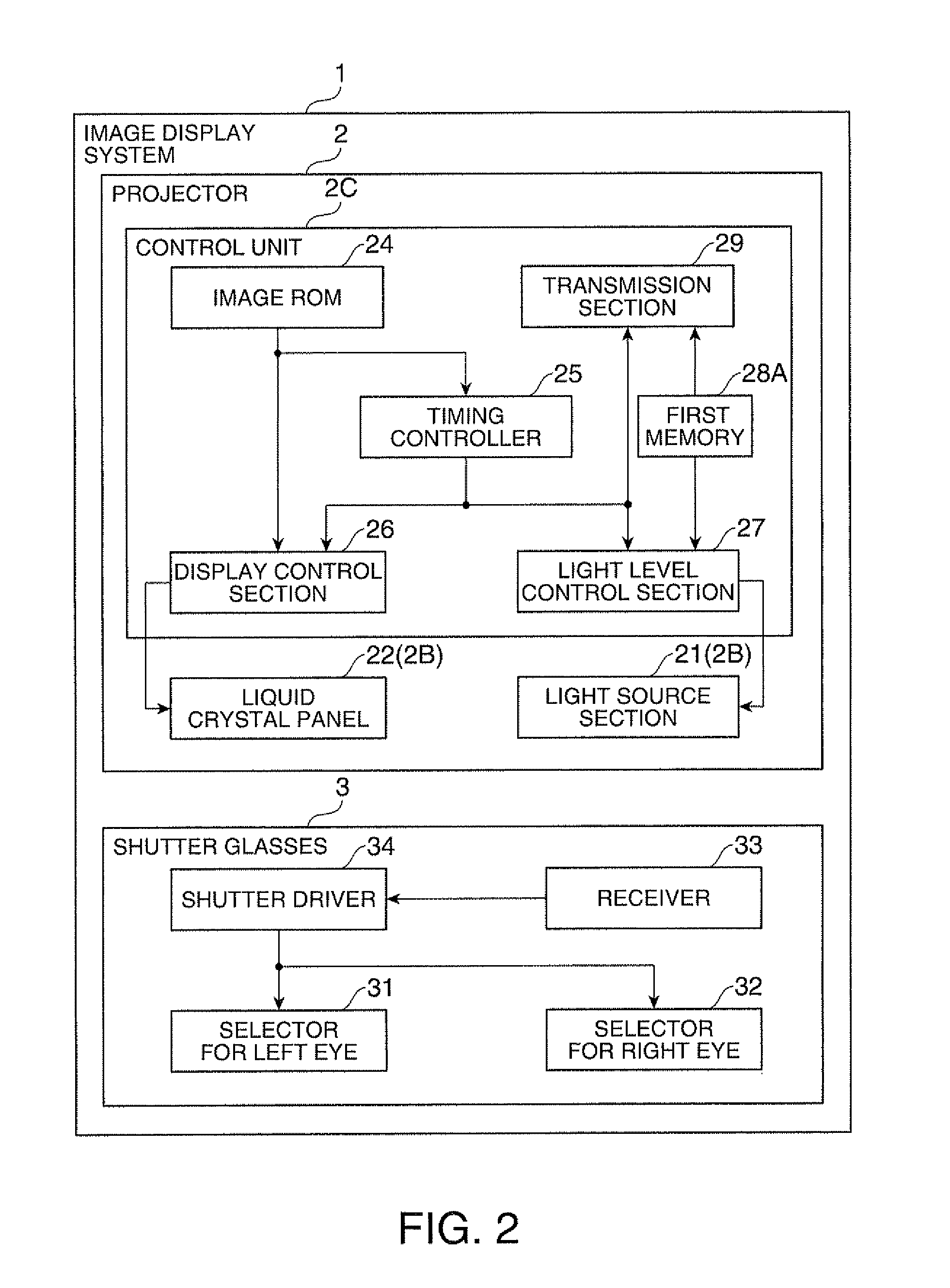
[0039]FIG. 2 is a block diagram diagrammatically showing the configuration of the image display system 1.

[0040]The image display system 1 projects and displays an image on a reflective screen Sc (FIG. 1) and allows a viewer to view the projected image stereoscopically. The image display system 1 includes a projector 2 as an image display apparatus and a pair of shutter glasses 3, as shown in FIG. 1 or 2.

Configuration of Projector

[0041]The projector 2 forms an image based on image information (image data) and projects the image on the screen Sc. The projector 2 includes an exterior housing 2A, which forms the exterior (FIG. 1), and an optical unit 2B (FIG. 2) and a control unit 2C (FIG. 2) accommodated in the exterior housing 2A, as shown in FIG. 1 or 2.

[0042]The optical un...

second embodiment

[0095]A second embodiment of the invention will next be described with reference to the drawings.

[0096]In the following description, the same components and members as those in the first embodiment described above have the same reference characters, and descriptions of these components and members will be omitted or simplified.

[0097]FIG. 5 is a block diagram diagrammatically showing the configuration of an image display system 1 in the second embodiment.

[0098]The present embodiment differs from the first embodiment in that the control unit 2C is provided with a second memory 28B as a change information storage section that stores change information on temporal change in the transmittance of the shutter glasses 3 (selector for left eye 31 and selector for right eye 32), as shown in FIG. 5. The present embodiment also differs from the first embodiment in that the light level control section 27 operates differently in accordance with the provision of the second memory 28B.

[0099]FIGS. 6...


PUM


Abstract

An image display apparatus comprise: a light source section; a light modulator that modulates light delivered from the light source section to display an image; a light level control section that adjusts the amount of light delivered from the light source section to the light modulator; and a display control section that updates the image displayed on the light modulator during a first period and a second period alternately switched therebetween. The display control section updated in the first period to a first image and a black image in this order and updates in the second period to a second image and the black image in this order. The light level control section sets the amount of light delivered from the light source section to be greater than that in other periods during a predetermined switching period including a point to switch between the first period and the second period.

Description

BACKGROUND[0001]1. Technical Field[0002]The present invention relates to an image display apparatus and an image display system.[0003]2. Related Art[0004]There has been a known image display system (stereoscopic video image display apparatus) including an image display apparatus that displays an image and a pair of shutter glasses worn by a viewer and allowing the viewer to stereoscopically view the image displayed by the image display apparatus through the shutter glasses (see JP-A-2009-232249, for example).[0005]FIGS. 7A to 7C describe the operation of an image display system of related art.[0006]Specifically, FIG. 7A is a timing chart showing the timing when image data are written along each scan line produced by an image display apparatus, and the vertical axis corresponds to the vertical direction of the image display apparatus (the vertical axis represents the positions of the uppermost scan line L1 to the lowermost scan line Ln). FIG. 7B is a timing chart showing the timing w...

Claims


Application Information

Patent Timeline
Patent Type & Authority Applications(United States)
IPC IPC(8): H04N13/04H04N13/363
CPCG02B27/2264H04N13/0459H04N13/0438H04N13/341H04N13/363G02B30/24
Inventor ENDO, TAKASHI
Owner SEIKO EPSON CORP
Why Eureka
Try Eureka