Imaging device for microscope

a microscope and imaging device technology, applied in closed circuit television systems, instruments, television systems, etc., can solve the problems of reducing the frame rate, difficult for users to perform framing operations, and difficult imaging operations such as framing (positioning) operations and focus operations, so as to reduce the time required and reduce the noise

Inactive Publication Date: 2012-03-22
OLYMPUS CORP
View PDF3 Cites 32 Cited by
  • Summary
  • Abstract
  • Description
  • Claims
  • Application Information

AI Technical Summary

Benefits of technology

[0014]In the imaging device for a microscope according to the present invention, the signal processing unit has a noise-reduction processing unit, and the signal processing setting unit determines a parameter of the noise-reduction processing unit so as to, in the case

Problems solved by technology

At the time of observation on the monitor, the decrease in the frame rate makes it difficult for a user to perform framing operations and focusing operations in a similar manner to the case where observation is perf

Method used


Image

  • Imaging device for microscope
  • Imaging device for microscope
  • Imaging device for microscope

Examples


first embodiment

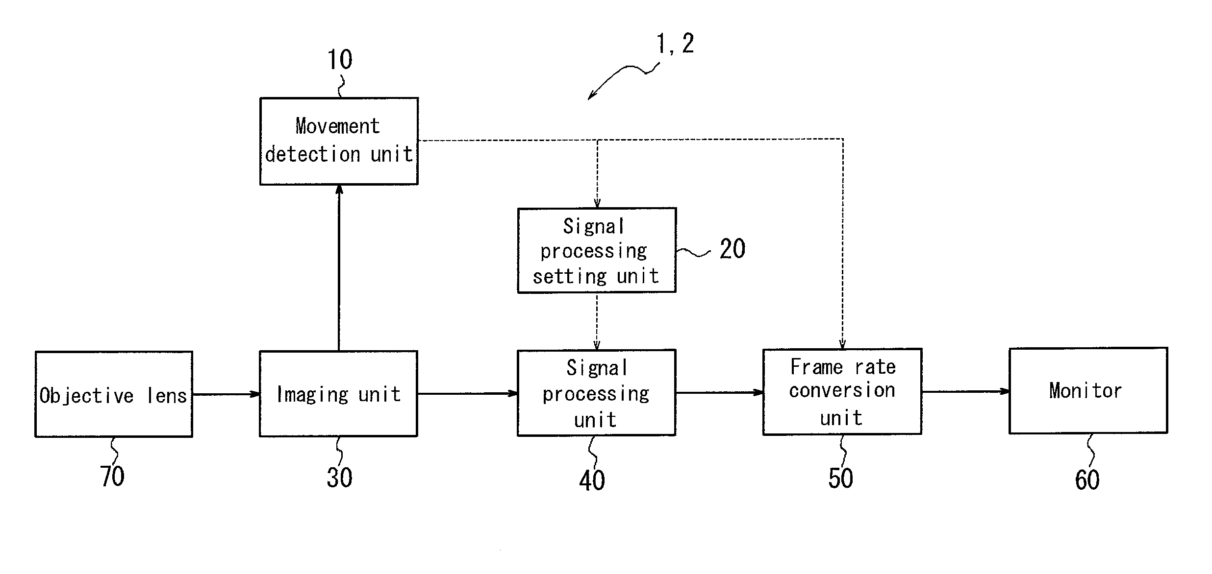
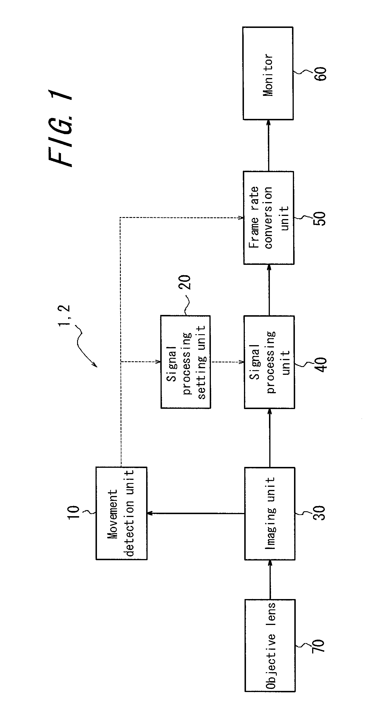
[0024]FIG. 1 is a block diagram schematically illustrating an imaging device for a microscope according to a first embodiment of the present invention. An imaging device 1 for a microscope includes a movement detection unit 10, a signal processing setting unit 20, an imaging unit 30, a signal processing unit 40, a frame rate conversion unit 50, a monitor 60 and an objective lens 70. In FIG. 1, the solid line represents a video signal and the dotted line represents a control signal.

[0025]The imaging unit 30 optically capture a video of an observation target formed by the objective lens 70, generates a video signal thereof, and outputs the video signal to the movement detection unit 10 and the signal processing unit 40.

[0026]The movement detection unit 10 detects movement (change) of “image” of the observation target in the video signal inputted from the imaging unit 30 to calculate a moving speed thereof, and, outputs information on the moving speed to the signal processing setting u...

second embodiment

[0054]Next, an imaging device for a microscope according to a second embodiment of the present invention will be described in detail with reference to the drawings. Note that the same reference numbers are denoted to the constituent elements same as those in the first embodiment, and explanation thereof will be omitted as appropriate.

[0055]An imaging device 2 for a microscope according to the second embodiment is the same as the imaging device 1 for a microscope according to the first embodiment, except for the configuration of the noise-reduction processing unit 43 of the signal processing unit 40. Therefore, the noise-reduction processing unit 43 of the imaging device 2 for the microscope will be described below. The noise-reduction processing unit 43 of the imaging device 2 for the microscope uses an inter-frame feedback filter. The inter-frame feedback filter reduces the nose by searching a portion having a high correlation between a previous frame that is stored in a memory and...

third embodiment

[0065]Next, an imaging device for a microscope according to a third embodiment of the present invention will be described in detail with reference to the drawings. Note that the same reference numbers are denoted to the constituent elements same as those in the first embodiment, and explanation thereof will be omitted as appropriate.

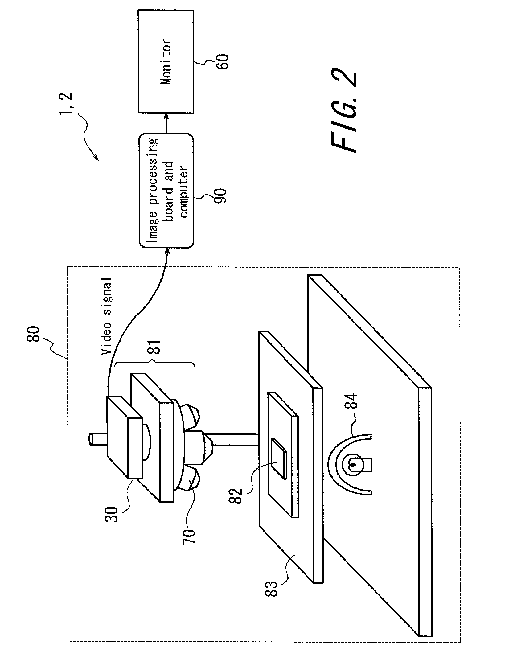
[0066]An imaging device 3 for a microscope according to this embodiment is different from the imaging device 1 for the microscope according to the first embodiment and the imaging device 2 for the microscope according to the second embodiment in that the imaging device 3 employs drive motors to move the X-Y stage 83 in the horizontal direction and move the imaging camera 81 in the vertical direction, and calculates the moving speed on the basis of a rotation amount of each of the drive motors. FIG. 6 is a block diagram schematically illustrating the imaging device for the microscope according to the third embodiment of the present invention. The movement...


PUM


Abstract

An imaging device including an imaging unit that obtains a video signal; a signal processing unit that processes the video signal; a movement detection unit that calculates a relative moving speed between the imaging unit and a stage in a first direction perpendicular to an optical axis of the imaging unit; a setting unit that determines a parameter such that time required for the signal processing is reduced where the relative moving speed is more than or equal to a threshold value; and, a frame rate conversion unit that selects between a process of increasing a frame rate of the video signal subjected to the signal processing where the relative moving speed is more than or equal to the threshold value, and a process of maintaining a current frame rate, to apply the selected process, wherein the signal processing unit applies the signal processing in accordance with the parameter.

Description

CROSS-REFERENCE TO RELATED APPLICATION[0001]The present application claims priority based on Japanese Patent Application No. 2010-209720 filed on Sep. 17, 2010, all of which disclosure is incorporated herein by reference.TECHNICAL FIELD[0002]The present invention relates to an imaging device for a microscope, which images a sample, applies signal processing and displays the sample on a monitor.RELATED ART[0003]Recently, at the time of observing with a microscope, a digital camera has been used by mounting it to a conventional optical microscope to perform observation, imaging and operation on a monitor and the like. In particular, it is considered that this tendency will further increase, as the number of a so-called all-in-one model increases which does not have any eyepiece. In this system, signal processing is applied so that fine structures can be observed more clearly on the monitor.[0004]However, a frame rate of images displayed on the monitor decreases as the amount of calcul...

Claims


Application Information

Patent Timeline
IPC IPC(8): H04N7/18
CPCG02B21/365
Inventor KODAIRA, NAOKOKOMIYA, YASUHIRO
Owner OLYMPUS CORP
Why Eureka
Try Eureka