
Housing mounted image intensifier tube

an image intensifier and housing technology, applied in the field of optical systems and image intensifier tubes, can solve problems such as image distortion

Active Publication Date: 2012-03-22
ELBIT SYSTEMS OF AMERICA LLC
View PDF2 Cites 9 Cited by
  • Summary
  • Abstract
  • Description
  • Claims
  • Application Information

AI Technical Summary

Problems solved by technology

Misalignment between the imaging device and its objective lens, caused by a housing of the optical system, results in distortion of an image that is being viewed by the optical system and the user of said system.

Method used


Image

  • Housing mounted image intensifier tube
  • Housing mounted image intensifier tube
  • Housing mounted image intensifier tube

Examples


Embodiment Construction

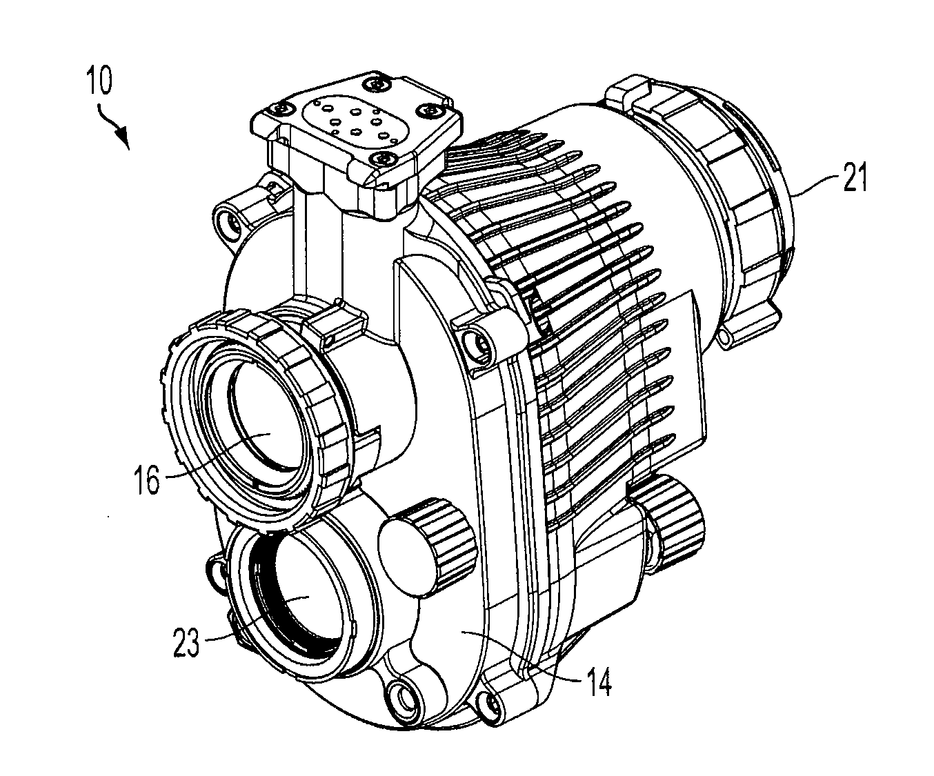
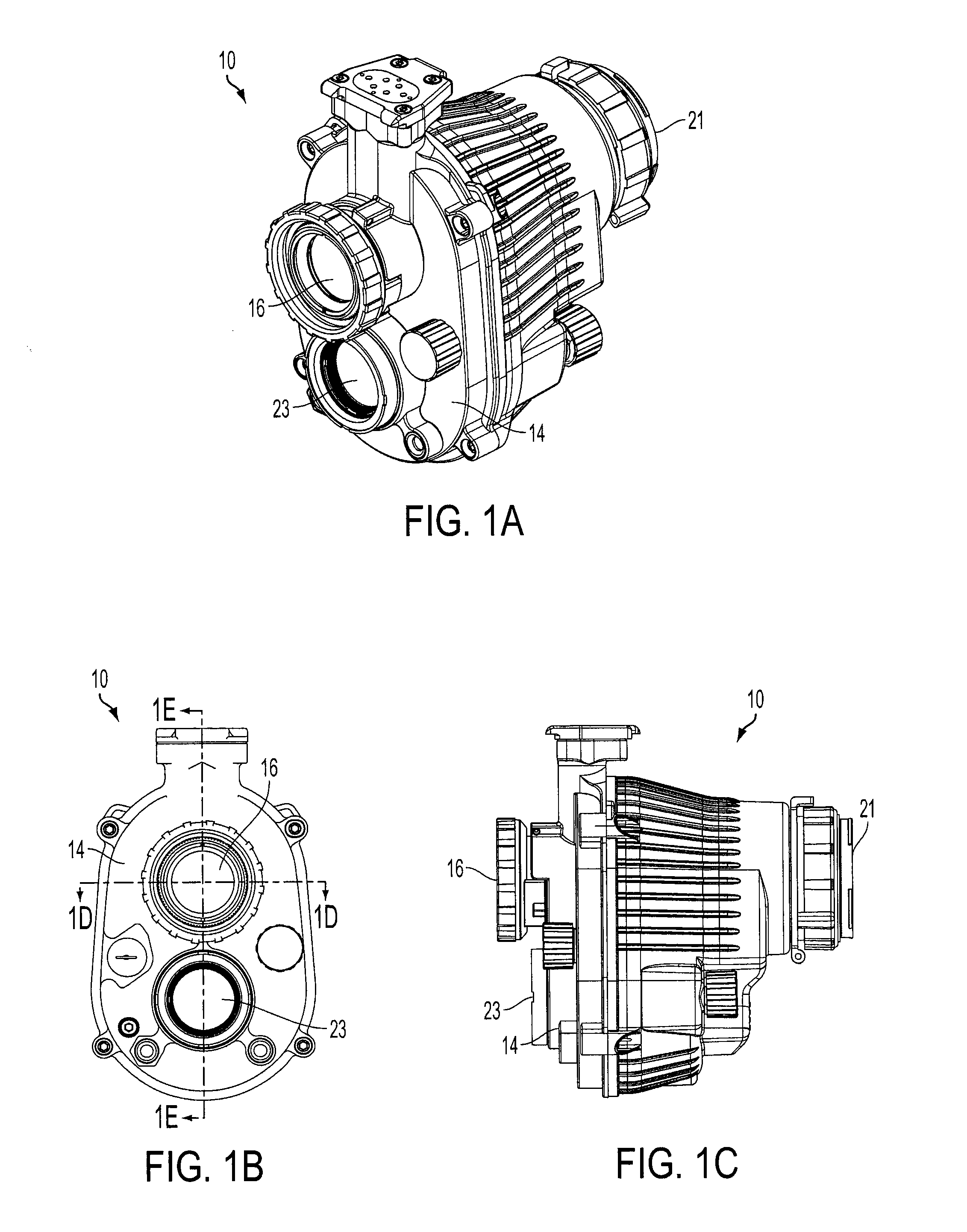
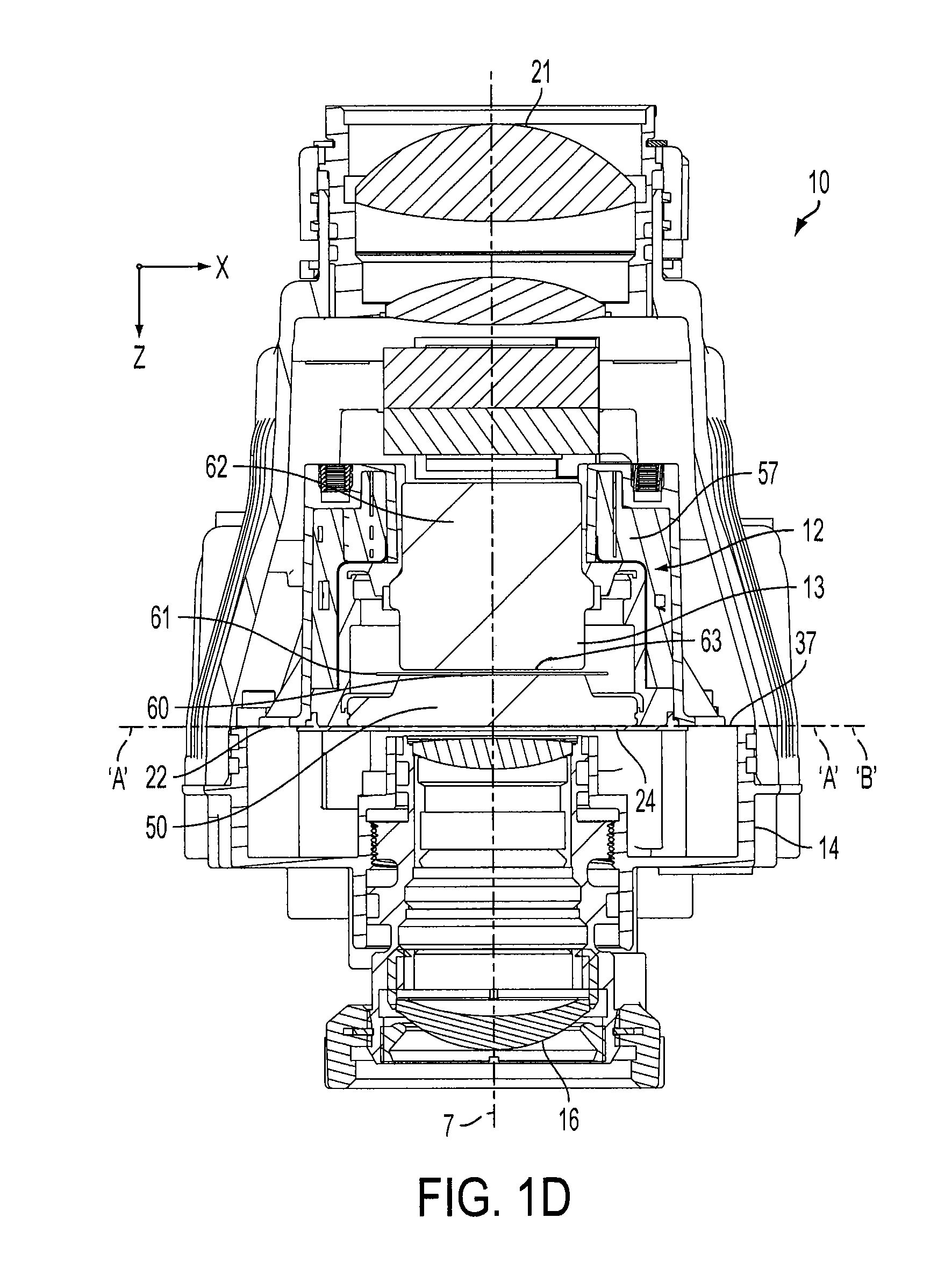
[0022]FIGS. 1A-1E depict a night vision monocular 10. Monocular 10 includes an objective lens assembly 16, and an infrared focal plane array of an infrared (IR) channel 23, which are each mounted to an optical bench 14. An eyepiece 21 is positioned opposite objective lens assembly 16. As best shown in FIGS. 1D and 1E, an image intensifier tube assembly 12 is mounted to optical bench 14 collinear with objective lens assembly 16. Mounting surface 22 of image intensifier tube assembly 12, which is defined by datum plane ‘A’, is mounted directly to mounting surface 37 of image optical bench 14, which is defined by datum plane ‘B.’

[0023]Image intensifier tube assembly 12 includes six basic components mounted within a housing 20, i.e., a glass faceplate 50, a photocathode 61 bonded to the glass faceplate 50, a micro-channel plate (MCP) 60, a phosphor screen 63, a fiber-optic inverter 62, and a power supply 57. The faceplate 50, the photocathode 61, the MCP 60, the phosphor screen 63, and ...


PUM

PropertyMeasurementUnit
optical axisaaaaaaaaaa
photosensitiveaaaaaaaaaa
absorbed energyaaaaaaaaaa

Abstract

An optical system includes an optical bench defining a mounting surface, an objective lens mounted to the optical bench, and an image intensifier tube. The image intensifier tube includes: (i) a housing defining an interior region and a mounting surface, and (ii) a photocathode bonded to a glass faceplate defining a faceplate surface, wherein the photocathode is positioned within the interior region of the housing, and wherein the mounting surface of the housing resides on the same plane as the faceplate surface. The mounting surface of the optical bench is mounted onto the mounting surface of the image intensifier tube housing such that the mounting surface of the optical bench resides on the same plane as the faceplate surface and the faceplate surface of the faceplate is the surface of the faceplate that is positioned closest to the objective lens.

Description

TECHNICAL FIELD[0001]This invention generally relates to an optical system, an image intensifier tube, and a method of mounting an image intensifier tube to an optical system.BACKGROUND OF THE INVENTION[0002]An imaging device must be properly aligned within an optical system to meet pre-determined line of sight, image alignment and resolution requirements of the optical system. The optical system may be a camera, camcorder, night vision goggle, or night vision scope, for example. The imaging device may be an image intensifier tube or a digital imaging device, such as a CCD (charge coupled device) or a CMOS (complementary metal oxide semiconductor), for example. Misalignment between the imaging device and its objective lens, caused by a housing of the optical system, results in distortion of an image that is being viewed by the optical system and the user of said system. There is a continuing need to further develop and refine imaging devices, methods for assembling imaging devices, ...

Claims


Application Information

Patent Timeline
Patent Type & Authority Applications(United States)
IPC IPC(8): G02B23/12B23P19/00
CPCG02B23/12Y10T29/49826H01J31/50
Inventor ADAMS, SCOTT J.GARRIS, WILLIAM ERICSCHLIRF, KEVINNEFF, TODD
Owner ELBIT SYSTEMS OF AMERICA LLC
Learn More