
Portable light

Inactive Publication Date: 2012-03-22
SANYO ELECTRIC CO LTD
View PDF3 Cites 22 Cited by
  • Summary
  • Abstract
  • Description
  • Claims
  • Application Information

AI Technical Summary

Benefits of technology

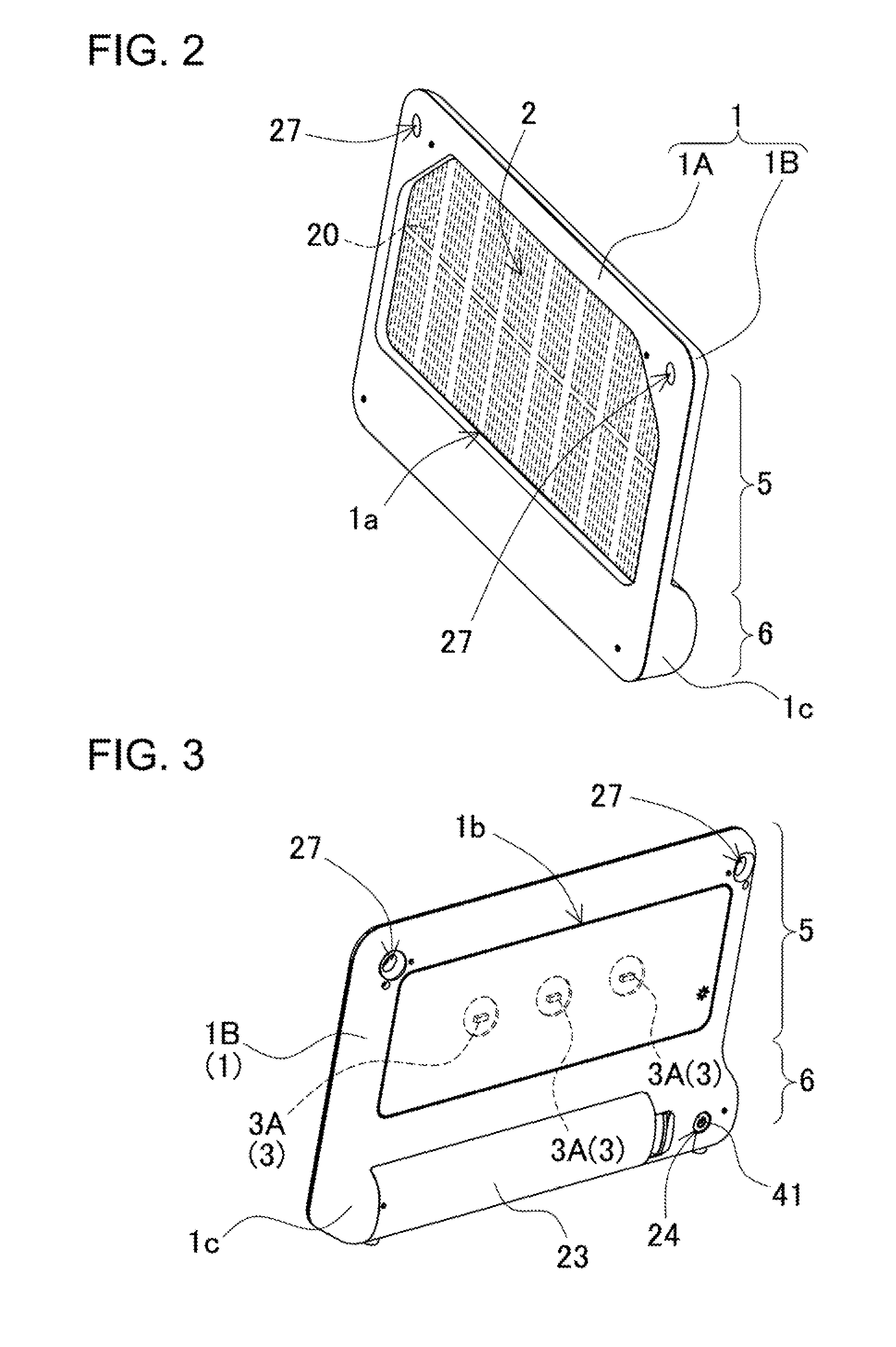
[0009]The portable light of the present invention is provided with an outer case 1, batteries 4 that can be charged and are housed inside the outer case 1, a solar panel 2 that charges the batteries 4, and a light source 3 illuminated by power from the batteries 4. The outer case 1 is provided with a flat-panel section 5 that contains the solar panel 2 and light source 3, and a battery compartment 6 that is thicker than the flat-panel section 5, is established projecting outward from the bottom edge of a surface of the flat-panel section 5, and has a bottom standing surface 7 enabling the portable light to stand alone.
[0010]The portable light described above has the characteristic that it can stand alone in a stable manner to increase solar panel surface area and power generation, and increase light source illumination area allowing it to shine brightly. Further, as a result of a low center-of-gravity due to the heavy batteries and the standing surface projecting outward from the front surface of the flat-panel section, the portable light has the characteristic that it can stand stably on its own while the surface area of the solar panel and light source is increased.
[0011]In the portable light of the present invention, the standing surface 7 can stand the flat-panel section 5 with the solar panel 2 surface inclined at an angle greater than a right angle with respect to horizontal and the light source 3 surface inclined at an angle less than a right angle with respect to horizontal. This portable light has the characteristic that solar panel output can be increased to efficiently charge the batteries, and the light source can shine brightly. This is because the solar panel is disposed facing upward and the light source is disposed pointing downward.

Problems solved by technology

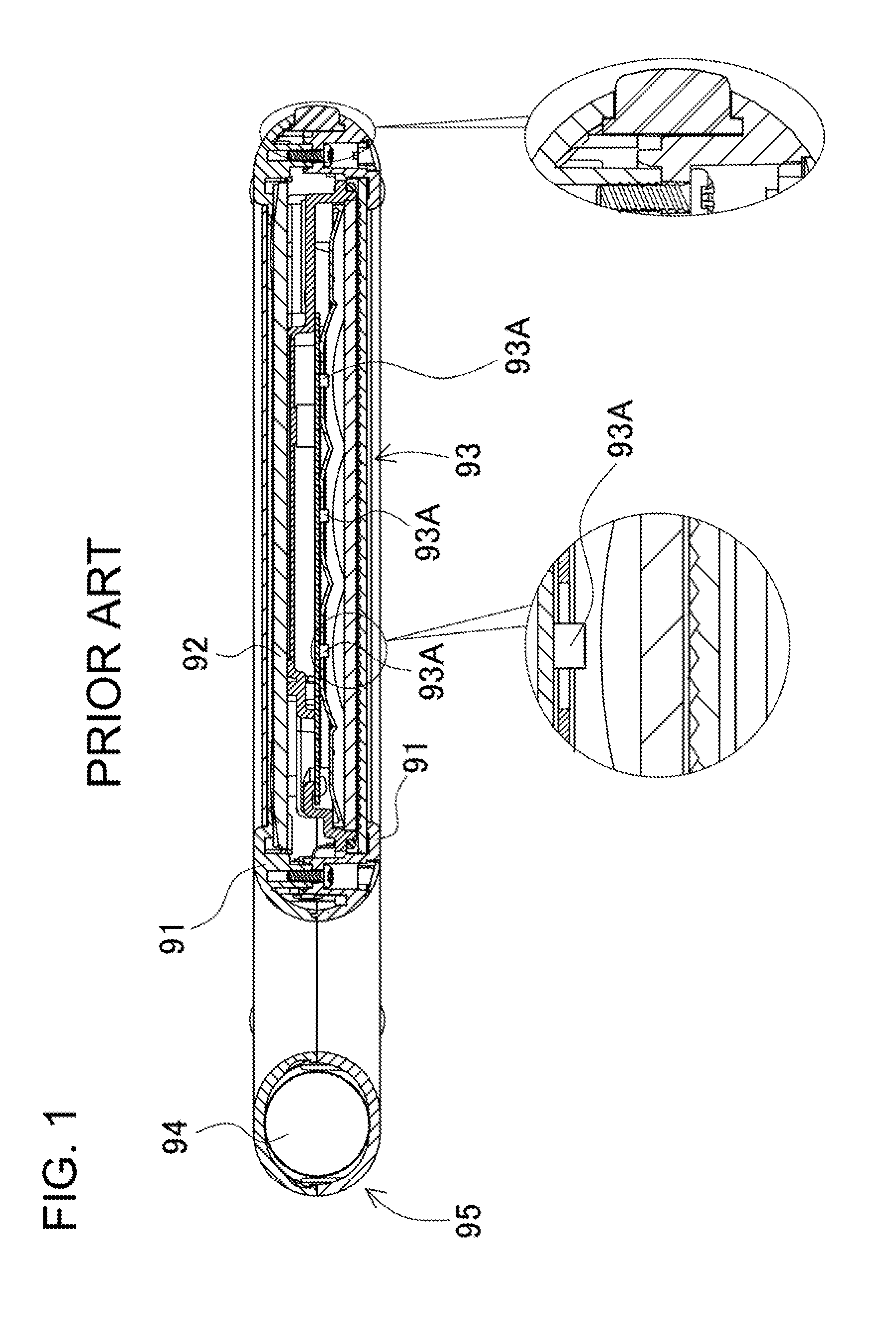
However, this portable light has the drawback that it is not convenient to operate when charging the battery with the solar panel or when using it as a source of illumination.
This is because the portable light cannot stand on its own in a stable manner, and standing the light for solar panel battery charging or illumination is troublesome.
It has the further drawback that when both sides are sandwiched by objects to hold the light upright, those objects reduce the effective surface area of the solar panel or reduce the light source illumination area preventing the light from shining brightly.

Method used


Image

  • Portable light
  • Portable light
  • Portable light

Examples


Embodiment Construction

[0036]The following describes embodiments of the present invention based on the figures. However, the following embodiments are merely specific examples of a portable light representative of the technology associated with the present invention, and the portable light of the present invention is not limited to the embodiments described below. Further, components indicated in the appended claims are in no way limited to the components indicated in the embodiments.

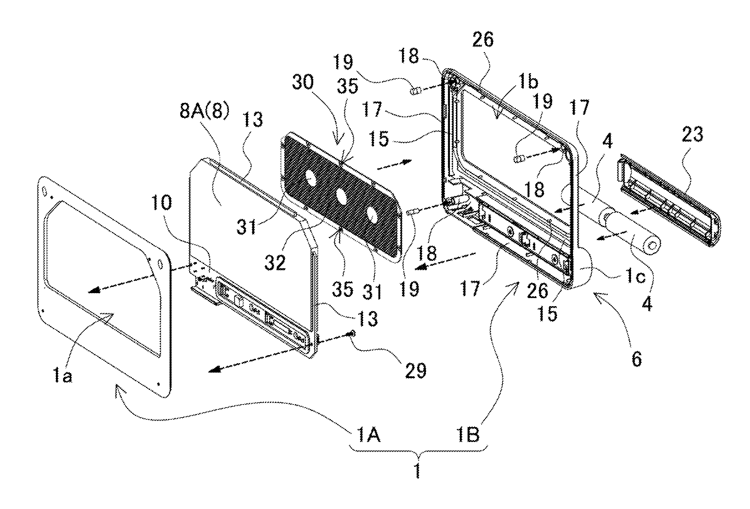
[0037]The portable light shown in FIGS. 2-9 is provided with an outer case 1, batteries 4 that can be charged and are housed inside the outer case 1, a solar panel 2 that charges the batteries 4, and a light source 3 illuminated by power from the batteries 4.

[0038]As shown inFIGS. 4-7, the outer case 1 is made up of a first case 1A and a second case 1B, and the solar panel 2 and light source 3 are disposed inside the first case 1A and second case 1B. The outer case 1 is made of plastic and is divided in the thickness directio...


PUM


Abstract

The portable light is provided with an outer case 1, batteries 4 that can be charged and are housed inside the outer case 1, a solar panel 2 that charges the batteries 4, and a light source 3 illuminated by power from the batteries 4. The outer case 1 is provided with a flat-panel section 5 that contains the solar panel 2 and light source 3; and a battery compartment 6 that is thicker than the flat-panel section 5, is established protruding outward from the bottom edge of a flat-panel section 5 surface, and has a bottom standing surface 7 that enables the flat-panel section 5 to stand upright on its own.

Description

BACKGROUND OF THE INVENTION[0001]1. Field of the Invention[0002]The present invention relates to a portable light that charges internal batteries via a solar panel and illuminates a light source.[0003]2. Description of the Related Art[0004]A light, which charges internal batteries with solar cells to illuminate a light source, effectively utilizes renewable energy for illumination. A feature of this type of illumination is its handy use during recreational activities or during electrical outage due to a natural disaster such as an earthquake or storm. Portable illumination has been developed for use in these types of applications.[0005]Refer to Japanese Laid-Open Patent Publication 2010-55789.[0006]As shown in FIG. 1, the portable light cited in JP 2010-55789 has an outer case 91 housing batteries 94 that can be charged, a solar panel 92 that charges the batteries 94, and light source elements 93A that are illuminated by battery 94 power. The outer case 91 has an overall flat-panel ...

Claims


Application Information

Patent Timeline
IPC IPC(8): F21L4/00F21V31/00
CPCF21L4/00F21S6/00F21S9/037H02S40/38F21Y2101/02H01L31/048Y02E10/50F21V31/005F21Y2115/10Y02E70/30
Inventor TOYA, SHOICHINAKASHO, TOSHIKI
Owner SANYO ELECTRIC CO LTD
Learn More