Steerable spine implant and system

a spine implant and system technology, applied in the field of spine implants and systems, can solve the problems of difficult direct approach to the spine, situ steering, etc., and achieve the effect of precise placemen

Inactive Publication Date: 2012-03-22
ALPHATEC SPINE INC
View PDF2 Cites 158 Cited by
  • Summary
  • Abstract
  • Description
  • Claims
  • Application Information

AI Technical Summary

Problems solved by technology

In some cases, the direct approach to the spine may be difficult and the current technologies do not allow for in situ steering of a spine implant.

Method used


Image

  • Steerable spine implant and system
  • Steerable spine implant and system
  • Steerable spine implant and system

Examples


Embodiment Construction

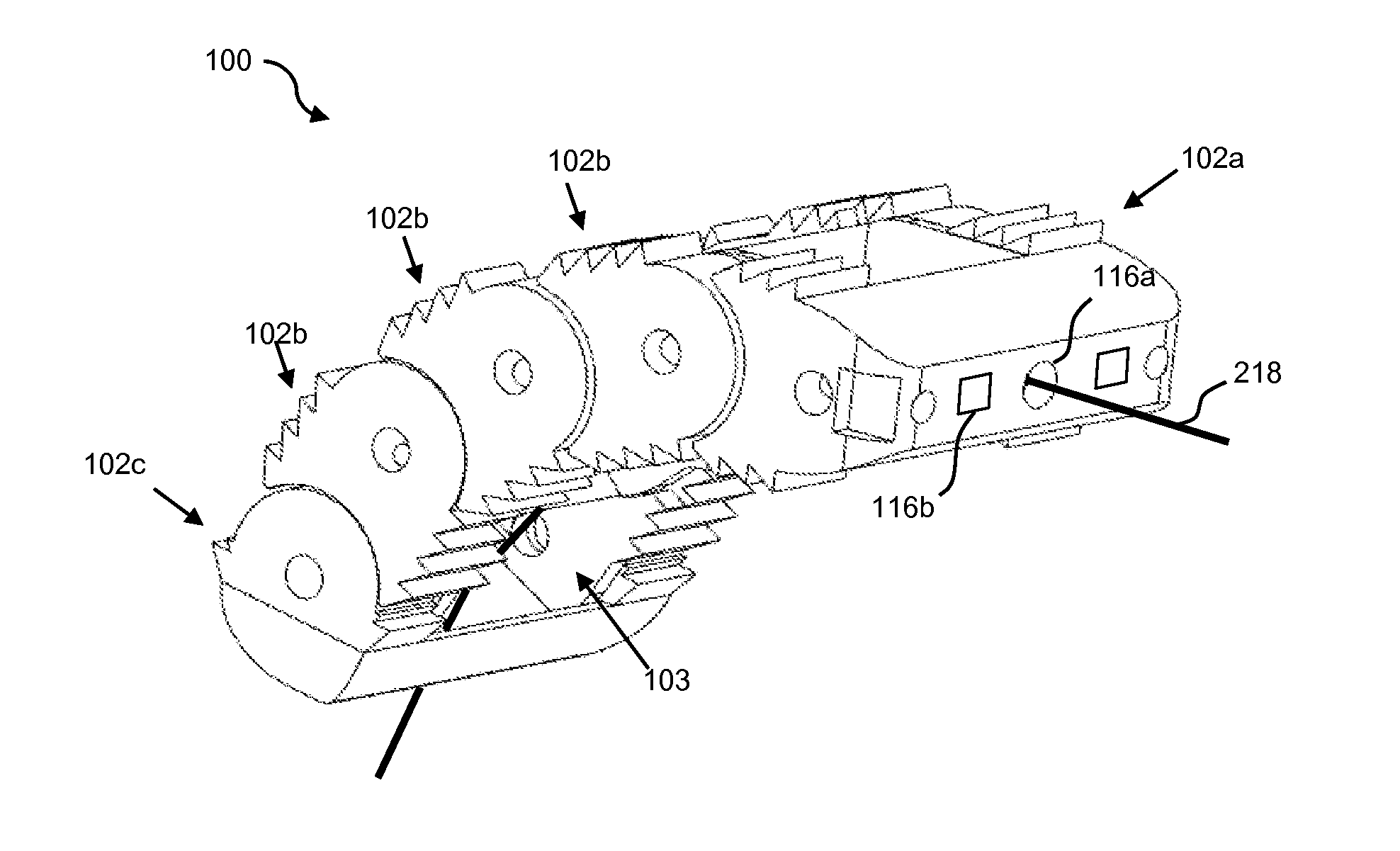
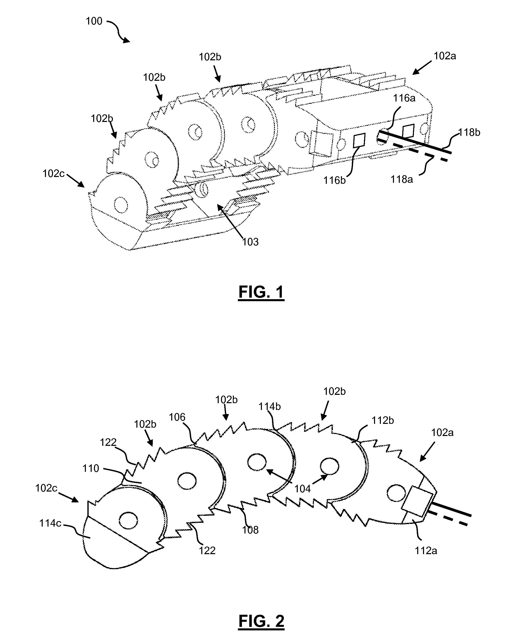
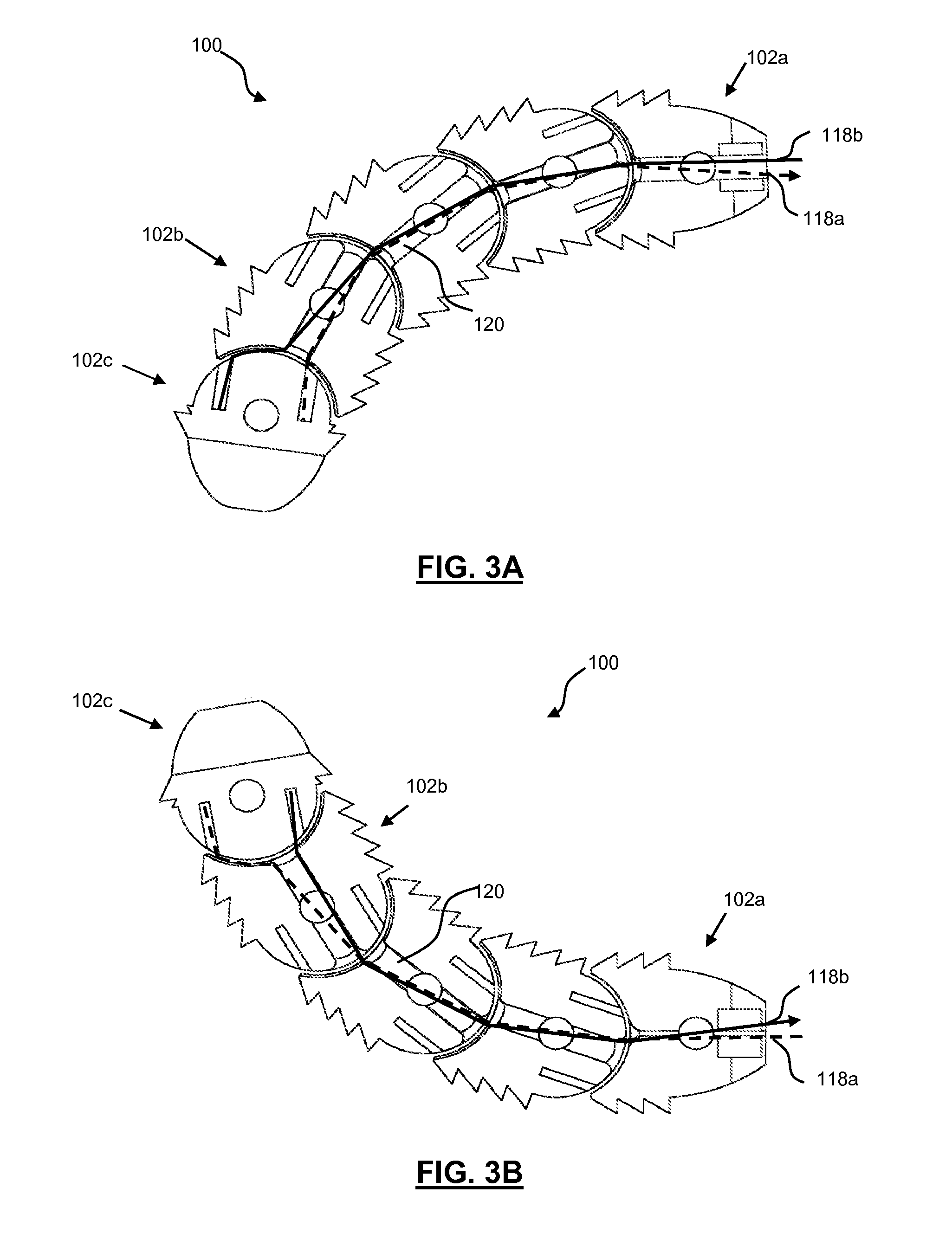
[0021]FIG. 1 is a perspective view and FIG. 2 is a side view showing one embodiment of a steerable spine implant 100 having a number of hinged links 102, including a proximal link 102a, one or more intermediate links 102b, and a distal link 102c. The links 102 are configured to rotatably link together. In some embodiments, proximal and distal end portions of the links have hinge features that interdigitate with each other and are held together with dowel or shear pins 104. This allows each of the links 102 to rotate with respect to each other. A plurality of tension members 118 are coupled to the links 102, such that pulling of the tension members rotates the links either clockwise or counterclockwise to steer the implant 100.

[0022]The implant 100 may be sized for use in many areas of the spine and may have varying height, length, thickness, and / or lordosis angle. In addition, each of the links 102 may have varying height, length, thickness, and / or lordosis angle. Links 102 may be a...


PUM


Abstract

Embodiments of the invention being disclosed are directed to a spine implant that allows for in situ adjustment or steering during implantation which allows for precise placement. The structure of the device is composed of a series of hinged link components connected by dowel or shear pins allowing for the links to rotate with respect to each other. The steering feature of the device is activated by a series of tension members connected or coupled to the links. As the tension members are placed in tension, typically by pulling the appropriate member, forces are placed on the individual links to actuate / rotate them in a clockwise or counterclockwise direction. By controlling the rotation of the links, the device may be steered in the desired direction.

Description

[0001]This application claims priority to U.S. Provisional Application 61 / 383,582, filed Sep. 16, 2010.FIELD OF THE INVENTION[0002]The present invention is directed to systems, methods, and devices applicable to surgery. More specifically, the present invention is directed to a steerable spine implant and system for use by medical personnel (i.e., doctor) in spinal and other surgical procedures.BACKGROUND OF THE INVENTION[0003]Vertebrae are the individual irregular bones that make up the spinal column—a flexuous and flexible column. There are normally thirty-three vertebrae in humans, including the five that are fused to form the sacrum (the others are separated by intervertebral discs) and the four coccygeal bones which form the tailbone. The upper three regions comprise the remaining 24, and are grouped under the names cervical (7 vertebrae), thoracic (12 vertebrae) and lumbar (5 vertebrae), according to the regions they occupy. This number is sometimes increased by an additional ...

Claims


Application Information

Patent Timeline
Patent Type & Authority Applications(United States)
IPC IPC(8): A61F2/44
CPCA61F2/4425A61F2002/4629A61F2002/2835A61F2002/30462A61F2002/30471A61F2002/30538A61F2002/30542A61F2002/30555A61F2002/30904A61F2002/4415A61F2002/443A61F2002/4475A61F2002/448A61F2002/4485A61F2002/4623A61F2002/4628A61F2/4611A61F2/4455A61F2002/3054A61F2/4603A61F2002/30593
Inventor PURCELL, THOMASLORIO, MORGAN
Owner ALPHATEC SPINE INC
Why Eureka
Try Eureka