Identification circuit and method for generating an identification bit using physical unclonable functions

a technology of identification circuit and function, which is applied in the direction of instruments, pulse techniques, basic electric elements, etc., can solve the problems of not being able to clone a device having a puf in a manner to generate the same puf output with another device, not being able to meet the requirements of security, and most applications have cost limitations that must be taken into accoun

Active Publication Date: 2012-03-22
INFINEON TECH AG
View PDF3 Cites 18 Cited by
  • Summary
  • Abstract
  • Description
  • Claims
  • Application Information

AI Technical Summary

Benefits of technology

[0011]A further embodiment includes a method for generating an identification bit, comprising the steps of: generating a first output signal from a first circuit which is a function of random parametric variations in the first circuit, generating a second output signal from a second circuit which is a function of random parametric variations in the second circuit, amplifying the difference between the first and the second output with a third circuit which can be operated in an amplification mode and in a latch mode and switch the third circuit in the latch mode to get a digital identification bit.

Problems solved by technology

It is nearly impossible to clone a device having a PUF implemented in a manner to generate the same PUF output with another device.
At the same time, most applications have cost limitations that must be taken into account.
For example, if a complicated authentication process requiring storage and computing resources were employed on an integrated circuit, the costs incurred may not justify the cost of security accomplished, particularly if the end product were a low cost and mass produced consumer product.
A disadvantage of the identification device described in U.S. Pat. No. 6,161,213 is the additional circuital complexity to derive the binary output data.

Method used


Image

  • Identification circuit and method for generating an identification bit using physical unclonable functions
  • Identification circuit and method for generating an identification bit using physical unclonable functions
  • Identification circuit and method for generating an identification bit using physical unclonable functions

Examples


Embodiment Construction

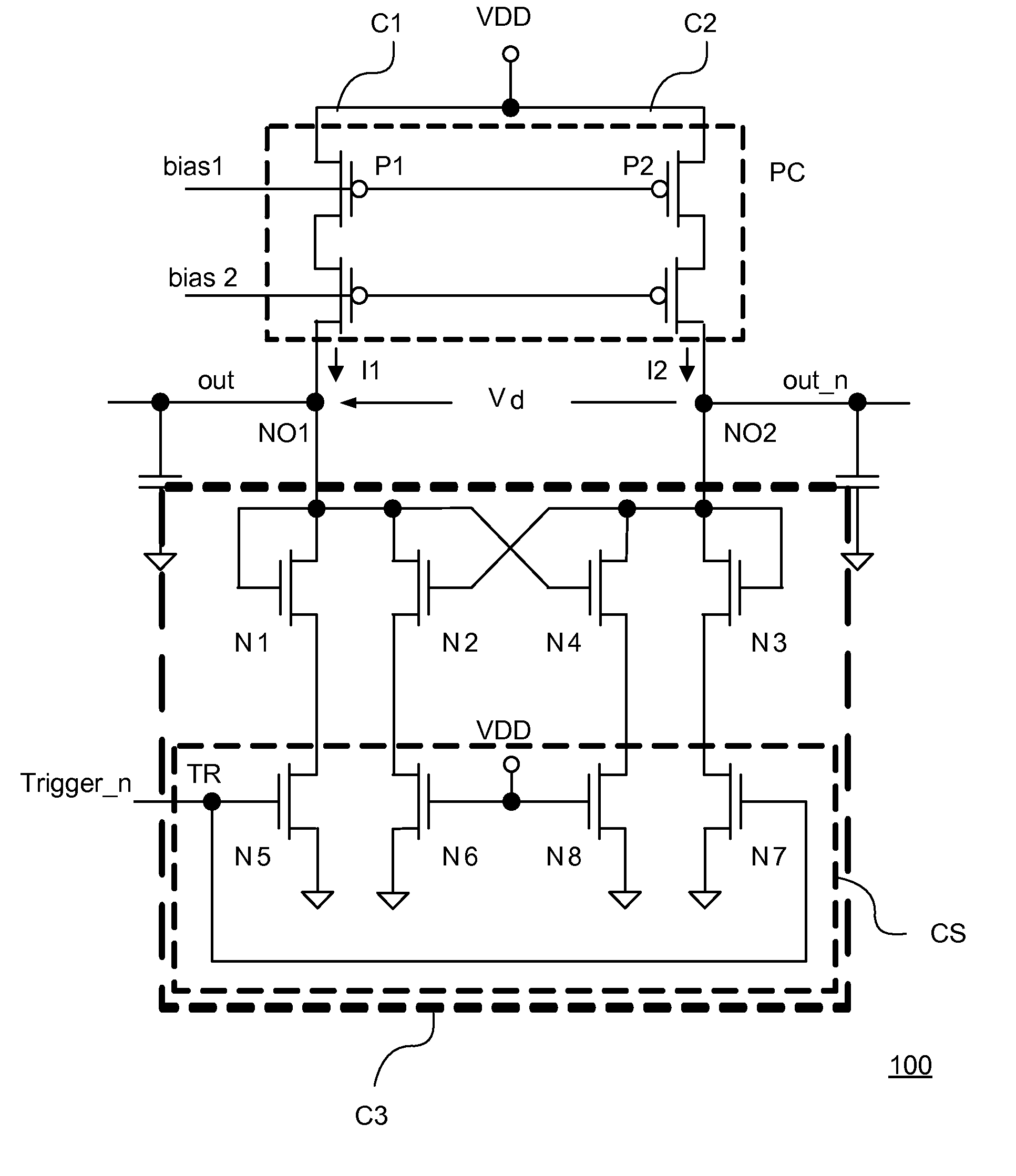
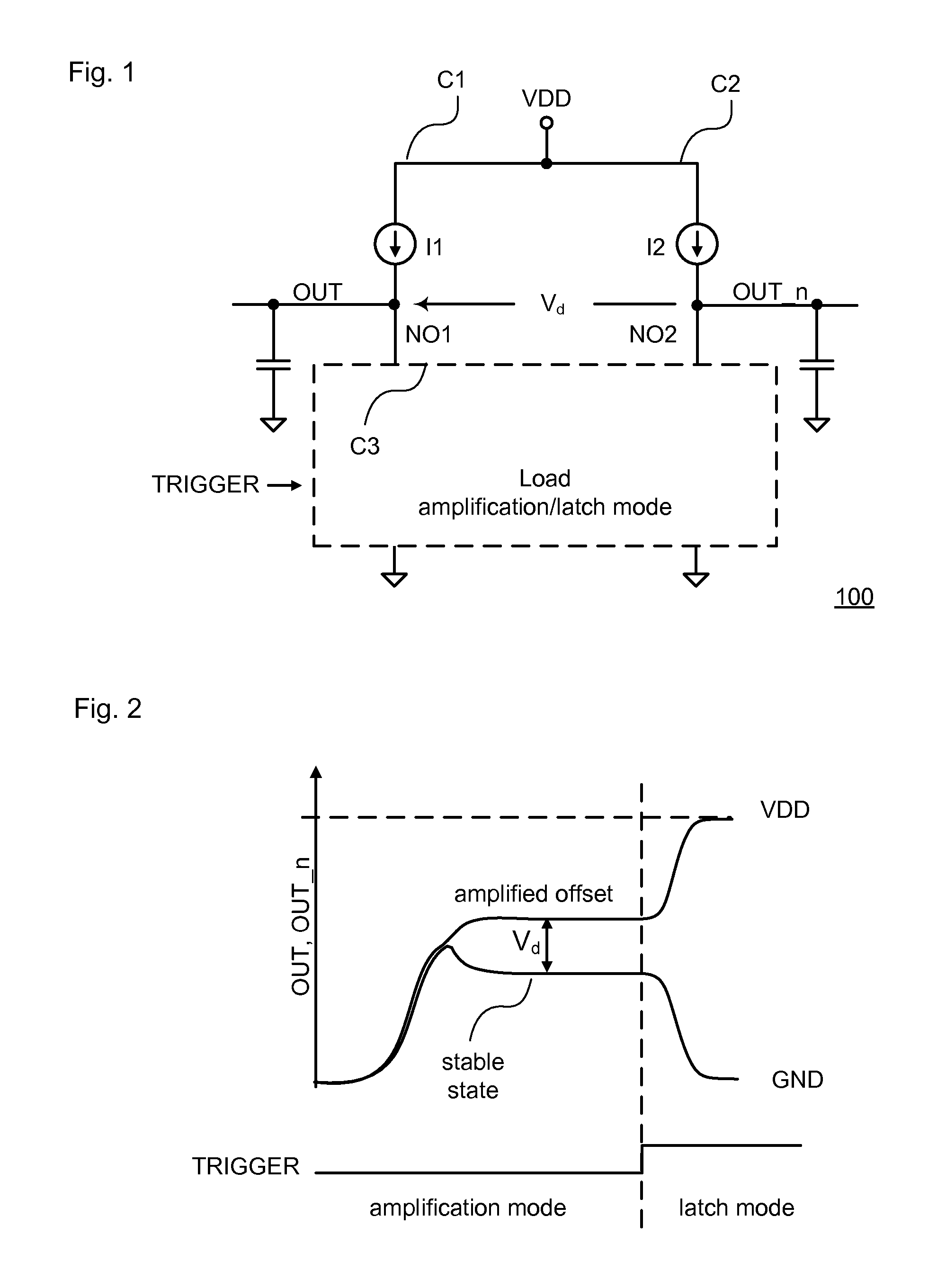
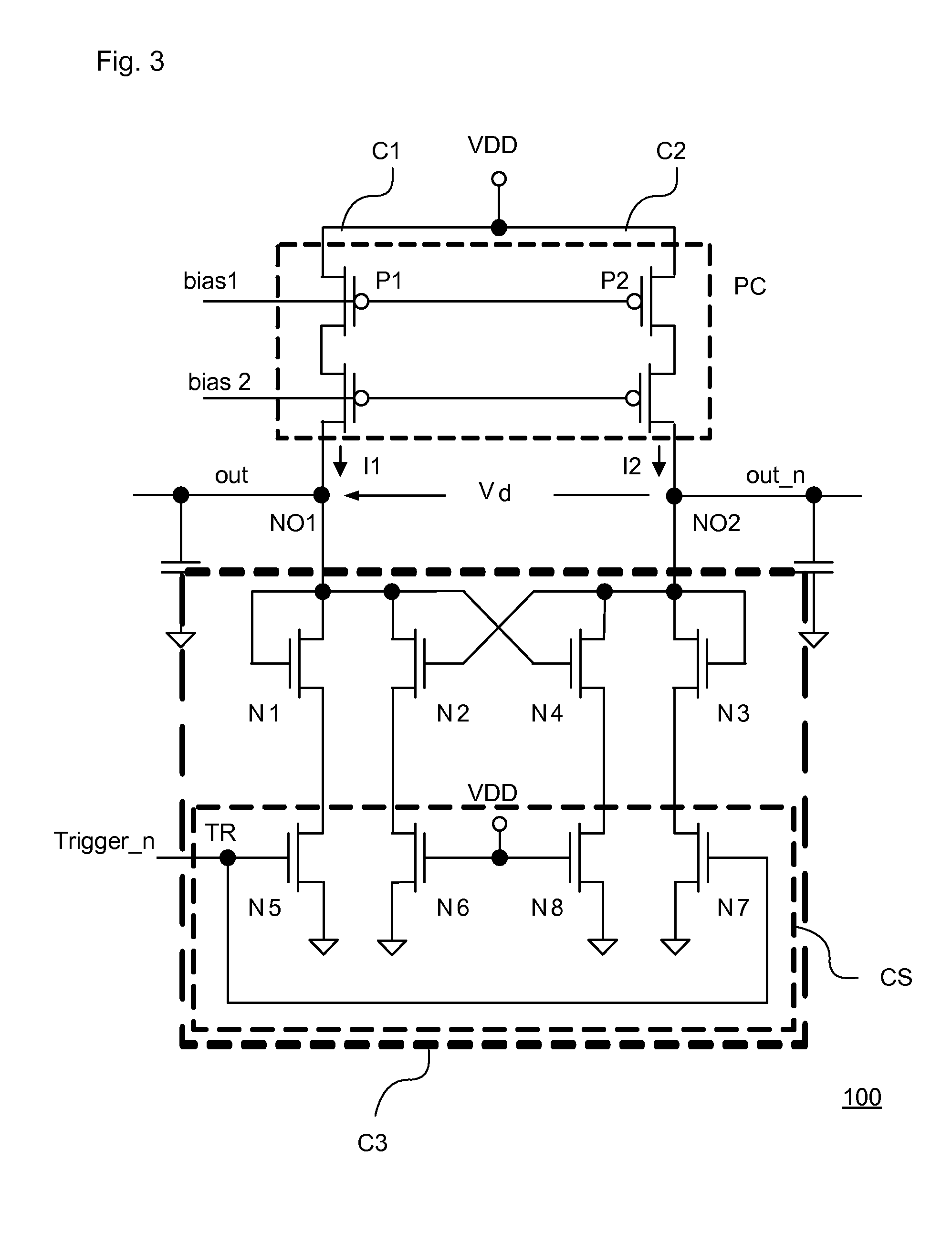
[0015]FIG. 1 shows an embodiment of an identification circuit 100 for generating an identification bit. The identification circuit 100 comprises a first circuit C1 to generate a current signal I1 which is provided via a node NO1 to a third circuit C3. Based on the current signal I1, a voltage signal OUT is generated at the node NO1 that is based on random parametric variations of one or more elements in the first circuit C1. A second circuit C2 is provided in the identification circuit 100 to generate a second current I2 which is provided via a node NO2 to the third circuit C3. The second current I2 is based on random parametric variations of at least one element in the second circuit C2. The third circuit C3 provides a load circuit and is capable to be operated in a first mode herein further referred to as an amplification mode and in a second mode herein further referred to as a latch mode. Depending on whether the third circuit C3 operates in an amplification mode or a latch mode...


PUM


Abstract

An embodiment of the present invention is an identification circuit installed on an integrated circuit for generating an identification bit, comprising a first circuit to generate a first output signal that is based on random parametric variations in said first circuit, a second circuit to generate a second output signal that is based on random parametric variations in said second circuit, a third circuit capable to be operated in an amplification mode and in a latch mode, wherein in said amplification mode the difference between the first output signal and the second output signal is amplified to an amplified value and, wherein in said latch mode said amplified value is converted into a digital signal.

Description

FIELD OF THE INVENTION[0001]The present invention relates to an identification circuit and a method for generating an identification bit using physically unclonable functions.BACKGROUND OF THE INVENTION[0002]The invention relates generally to technology for generating a unique identification number for electronically securing electronic devices and, more particularly, to an identification circuit and a method for generating an identification bit using physically unclonable functions (PUFs). PUFs are known in the art to be implemented by circuits, components, processes or other entities capable of generating an output, such as a digital bit, word or a function that is resistant to cloning. Typically, the PUF can be generated based on inherent physical characteristics of a device such as for example individual physical characteristics of a transistor such as a threshold voltage of the transistor which varies due to local process variations during manufacturing. There is no need to sto...

Claims


Application Information

Patent Timeline
Patent Type & Authority Applications(United States)
IPC IPC(8): G06F1/02H03K19/00
CPCH01L23/544H01L2223/5444H01L2223/54473H03K19/003H01L2924/0002H01L2924/00
Inventor BUCCI, MARCOLUZZI, RAIMONDO
Owner INFINEON TECH AG
Why Eureka
Try Eureka