Test head assembly for use in testing protective masks

Active Publication Date: 2012-03-29
HAMILTON ASSOCS
View PDF2 Cites 5 Cited by
  • Summary
  • Abstract
  • Description
  • Claims
  • Application Information

AI Technical Summary

Benefits of technology

[0008]Another object of a preferred embodiment of the present invention is to provide a test head assembly for use in testing protective masks that allows a protective mask to be readily and properly mounted about the test head assembly.
[0009]A further object of a preferred embodiment of the present invention is to provide a test head assembly designed to allow the mask tester to more rapidly reach a prerequisite test condition, e.g., 6 inches of vacuum.
[0010]Yet another object of a preferred embodiment of the present invention is to provide a test head assembly that greatly improves the response time of the mask tester.
[0011]Still a fur

Problems solved by technology

The disadvantages inherent in previously known test heads can have dramatic and adverse impacts on the mask testing process as explained below.
Conventional wisdom of forming the test head such that the test head closely resembles the corresponding portion of the human body has significant and dramatic adverse consequences on the protective mask testing process.
For example, test heads previously used to test neck seal type protective masks do not allow a neck seal type protective mask to be readily and properly installed over the test head.
Rather, it is relatively time consuming and cumbersome to mount a neck seal type protective mask about previously known test heads configured to closely replicate the human head and neck region.
This significant disadvantage severely limits the number of masks that can be tested in a given time interv

Method used


Image

  • Test head assembly for use in testing protective masks
  • Test head assembly for use in testing protective masks
  • Test head assembly for use in testing protective masks

Examples


Example

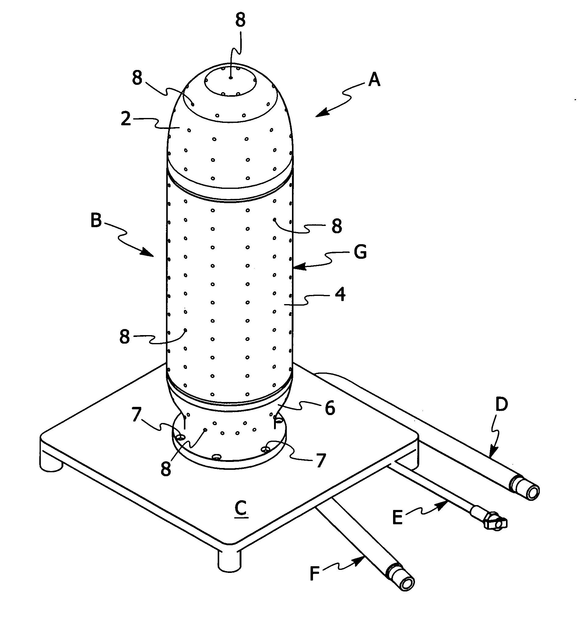
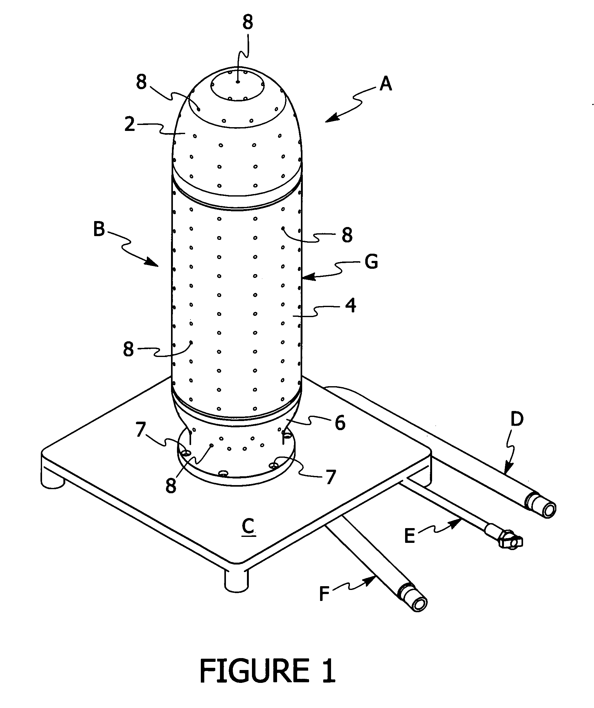
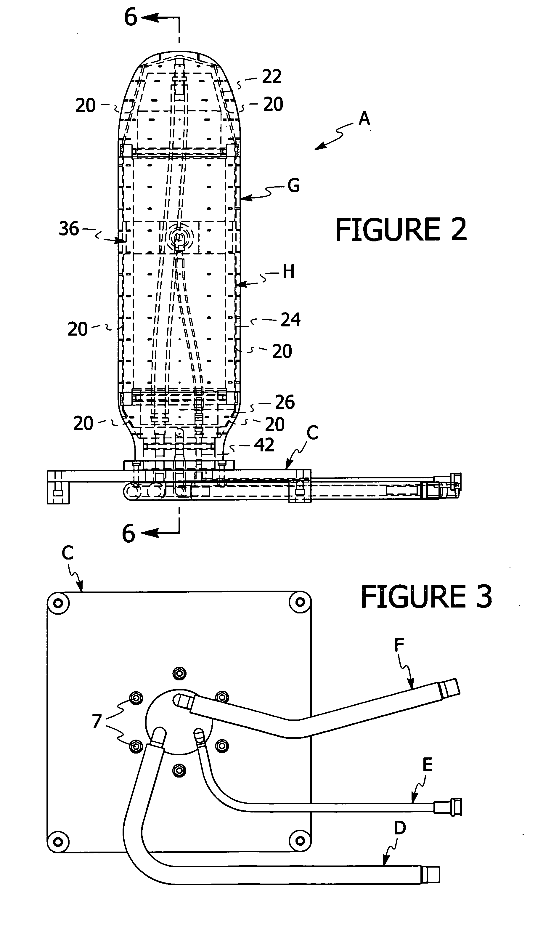
[0030]The preferred form of the test head assembly will now be described with reference to FIGS. 1-7. The appended claims are not limited to the preferred forms and no term and / or phrase used herein is to be given a meaning other than its ordinary meaning unless it is expressly stated otherwise. An optional test shroud that may be used in connection with the preferred form of the test head assembly will be described with references to FIGS. 8-10.

FIGS. 1 Through 7

[0031]Referring to FIG. 1, a preferred form of freestanding (i.e., a stand alone item that is operably connected to a mask tester not shown) test head assembly A is illustrated. It should be noted that the present invention is not limited to a freestanding test head assembly. Rather, the present invention includes but is not limited to a test head assembly that is mounted on a mask tester. It should be further noted that the test head assembly of the present invention can be used with a multitude of different mask testers. B...


PUM


Abstract

An apparatus for use in testing a protective mask for leaks. The apparatus includes a test head assembly for supporting at least a portion of a protective mask to be tested for leaks. The test head assembly may be freestanding or it may be mounted directly on the mask tester. Preferably, the test head assembly includes a test head having a test space. The test space is operably associated with a mask tester such that a fluid from the test space is directed to the mask tester for analysis to determine if a leak exists in the mask. The test space is generally coextensive with the inner surface of the protective mask being tested. Although the test space is generally coextensive with the inner surface of the protective mask being tested, it is designed such that it has minimal volume to enhance the testing process by expediting test response time, reducing the time period it takes for a mask tester to reach one or more prerequisite test conditions (e.g., a predetermined vacuum), eliminate or greatly reduce lag time when the mask tester is operating in the probe mode (i.e., the mode used to isolate the location of a leak) and prevent dilution of challenge concentration. Preferably, the test is shaped to permit a protective mask to be readily mounted on the test head in a fluid tight manner. Preferably, the test head is formed from two or more removable sections to allow the size of the test head to be readily modified without replacing the entire test head. An optional perfect mask or test shroud may be mounted about the test head to ensure that the mask tester is not erroneously detecting leaks in a protective mask being tested.

Description

FIELD OF THE INVENTION[0001]The present invention is directed to a test head assembly or device for use with a mask tester to determine whether one or more leaks is present in one or more portions of a protective mask. The test head assembly can be used in testing military and commercial type protective masks. The test head assembly of the present invention may be used with a multitude of different mask testers including but not limited to mask testers utilizing the following testing techniques: (i) challenge concentration; (ii) vacuum or pressure decay; (iii) controlled negative pressure while monitoring flow; and (iv) ultrasonic.BACKGROUND OF THE INVENTION[0002]Protective masks have been used for sometime in both civilian and military applications. These protective masks are designed to protect the wearer from nuclear, biological, chemical agents, fumes, aerosols, gases and airborne contaminants. Hence, it is extremely important that the mask be properly tested to ensure that it w...

Claims


Application Information

Patent Timeline
IPC IPC(8): G01M3/04
CPCG01M3/26
Inventor HANSON, ERICHODGE, COLIN GORDONMCCURDY, GARY WARRENOLVERA, GILBERT
Owner HAMILTON ASSOCS
Why Eureka
Try Eureka