

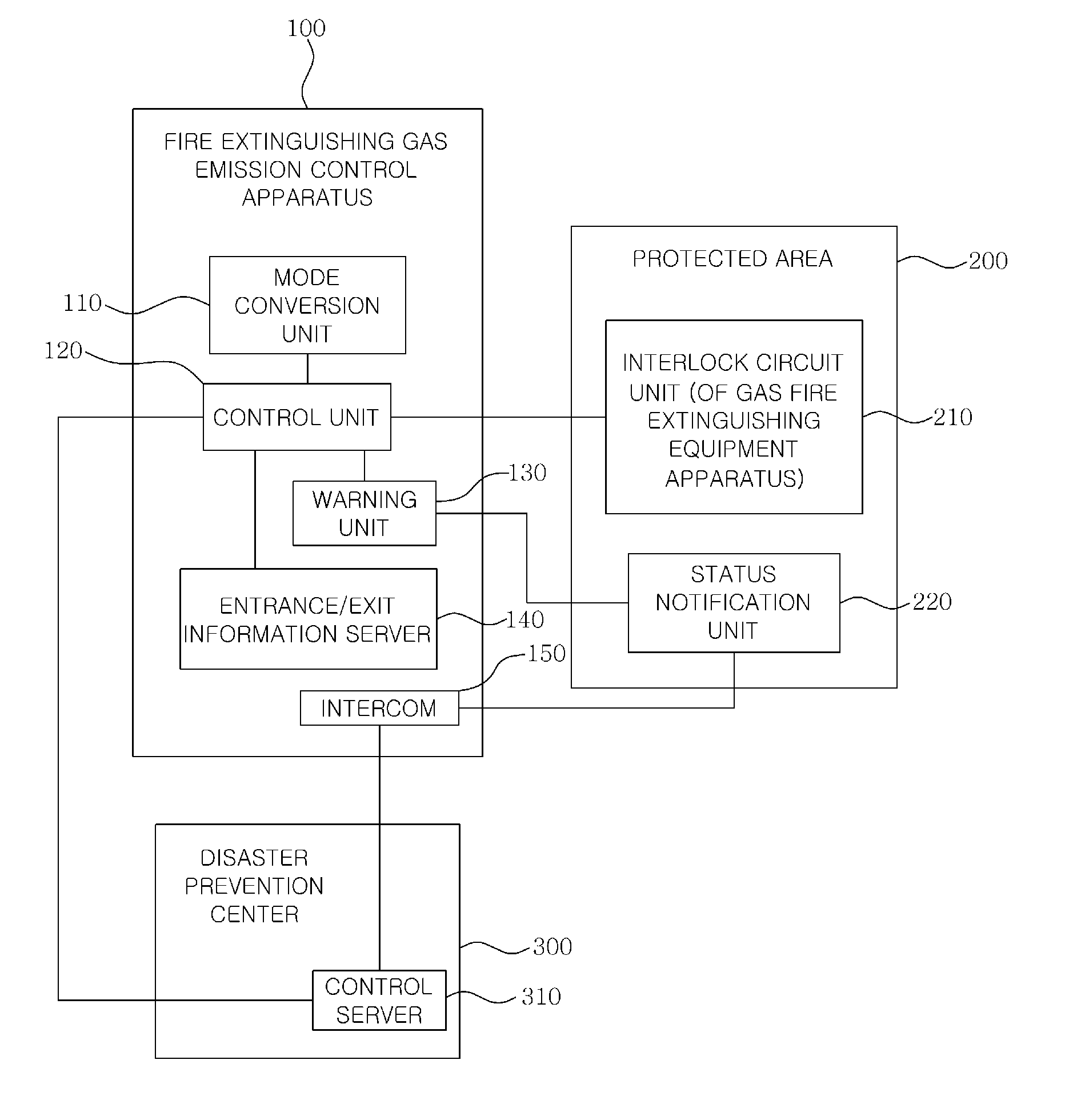
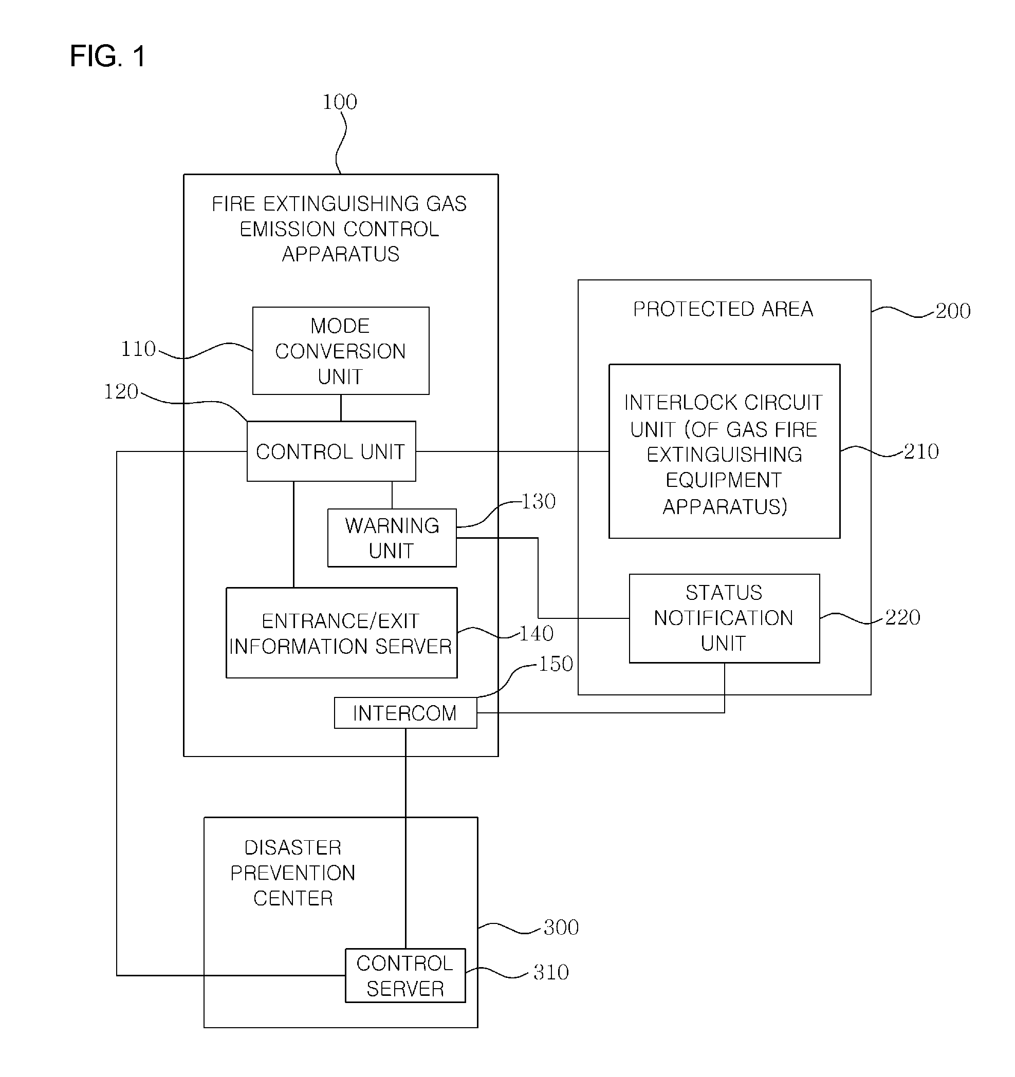
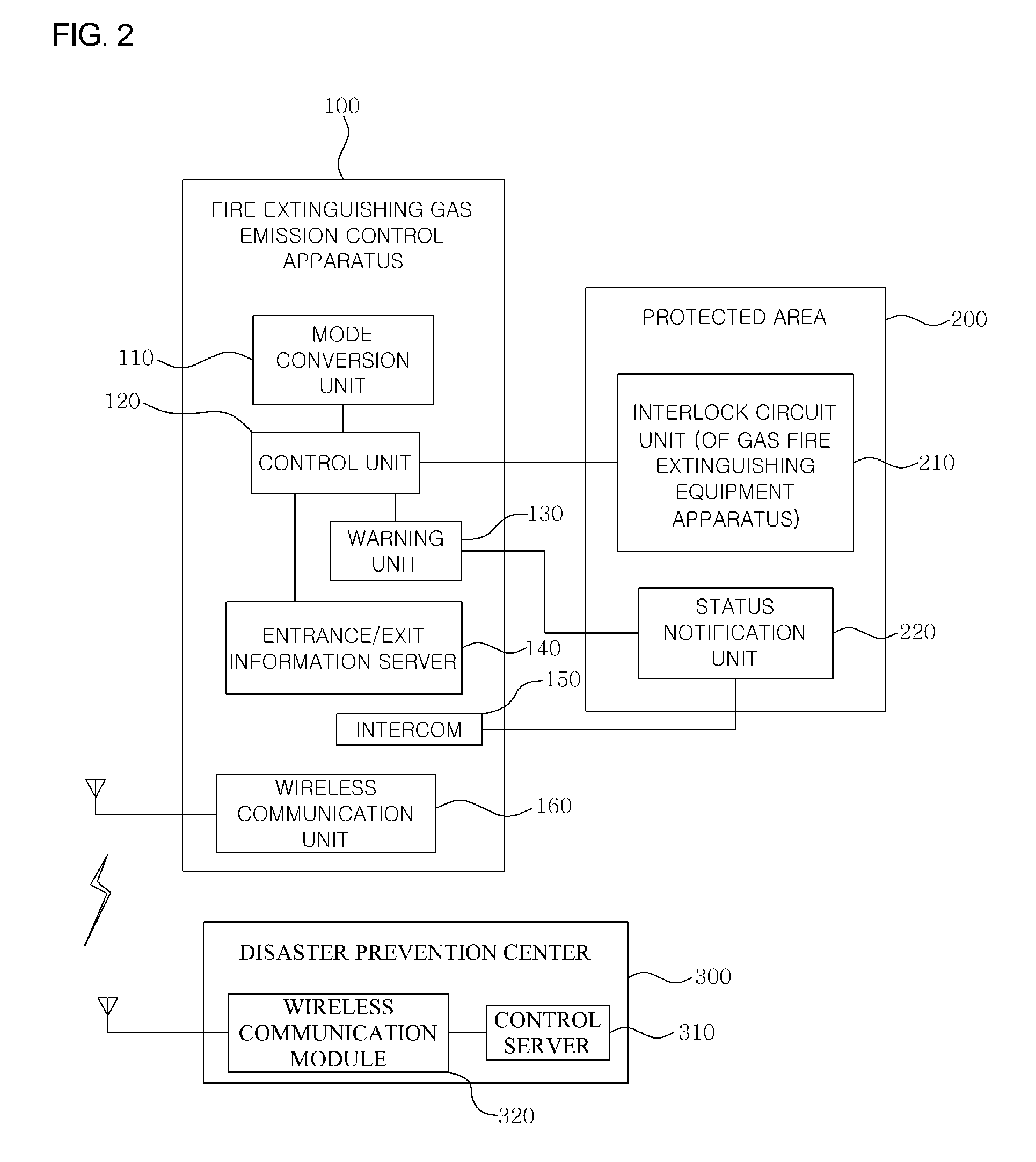
Fire extinguishing gas emission control apparatus
a technology of emission control apparatus and fire extinguishing gas, which is applied in the direction of self-acting watering devices, packaging, horticulture, etc., can solve the problems of existing fire extinguishing gas emission control apparatuses and abnormal or normal emission of fire extinguishing gas
- Summary
- Abstract
- Description
- Claims
- Application Information
AI Technical Summary
Benefits of technology
Problems solved by technology
Method used
Image

Examples
Embodiment Construction
[0023]Other details of embodiments are included in detailed description and the accompanying drawings.
[0024]The advantages, features, and methods of accomplishing the invention will be clearly explained with reference to the embodiments which will be described in detail with reference to the accompanying drawings.
[0025]However, the present invention is not limited to the disclosed embodiments below and may be implemented using various other embodiments which are different from each other. The present embodiments are provided to only complete the disclosure of the present invention and to completely inform those skilled in the art of the scope of the present invention. The present invention is to be defined by the scope of the claims. Reference now should be made to the drawings, throughout which the same reference numerals are used to designate the same or similar components.
[0026]The present invention will be described with reference to the drawings used to describe the fire exting...
PUM
 Abstract
Description
Claims
Application Information