Tool-free metal conduit connector and related methods

a technology of metal conduit and connector, which is applied in the direction of pipes, couplings, mechanical equipment, etc., can solve the problems of not being able to thread, and the required pull-out force is typically greater than the average person could reasonably exer

Active Publication Date: 2012-03-29
REPUBLIC CONDUIT INC
View PDF5 Cites 15 Cited by
  • Summary
  • Abstract
  • Description
  • Claims
  • Application Information

AI Technical Summary

Problems solved by technology

However, EMT is not capable of being threaded.
However, the required pull-out force is typically greater than the average person could reasonably exert without the aid of tools.

Method used


Image

  • Tool-free metal conduit connector and related methods
  • Tool-free metal conduit connector and related methods
  • Tool-free metal conduit connector and related methods

Examples


Embodiment Construction

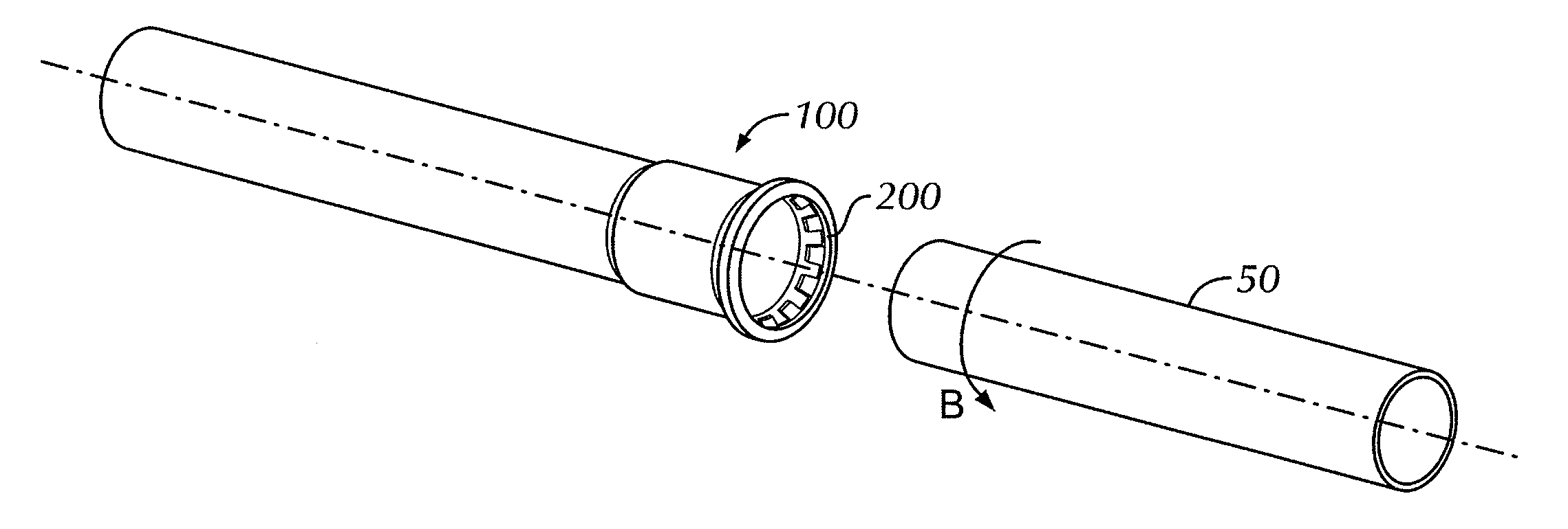
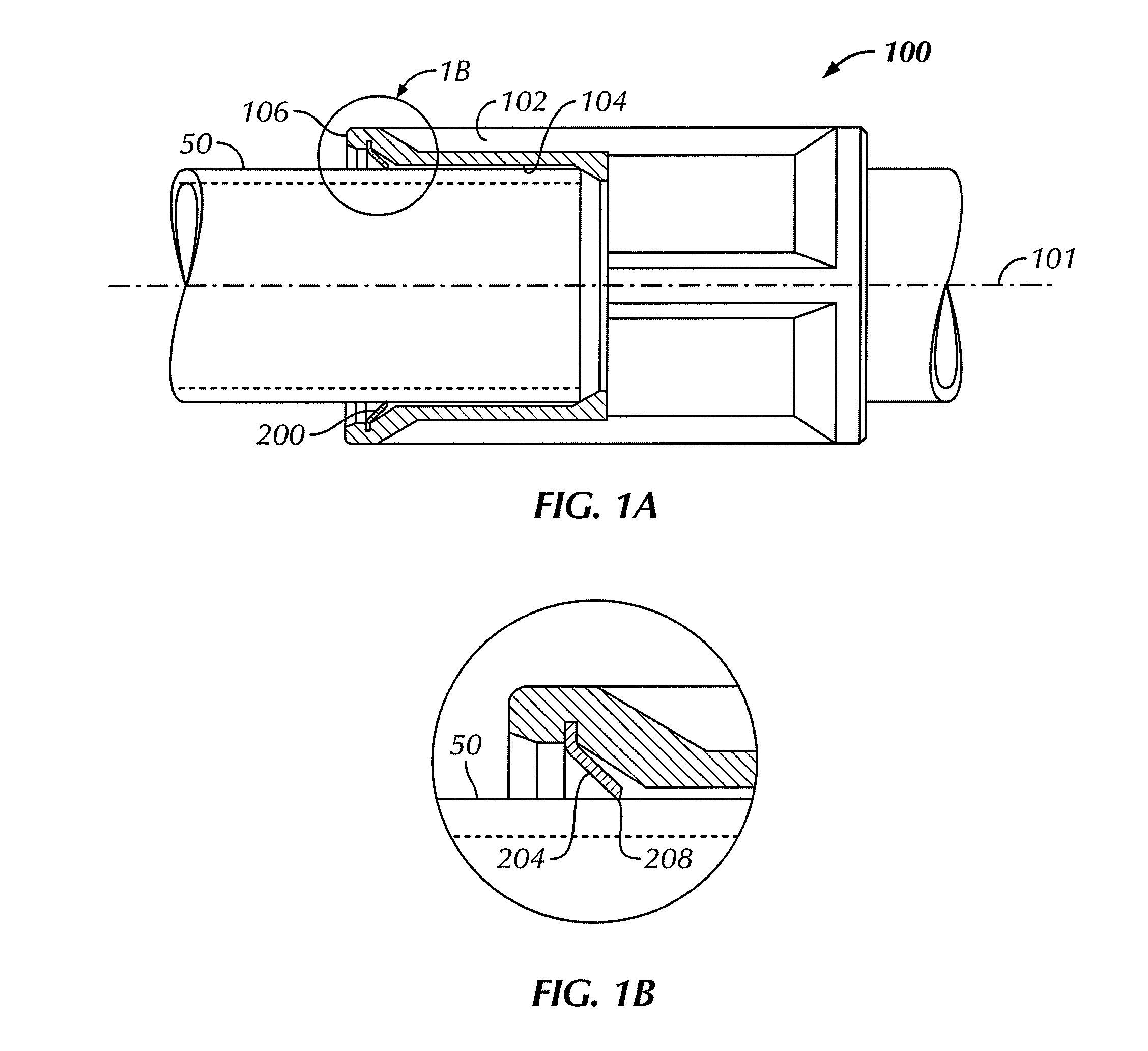
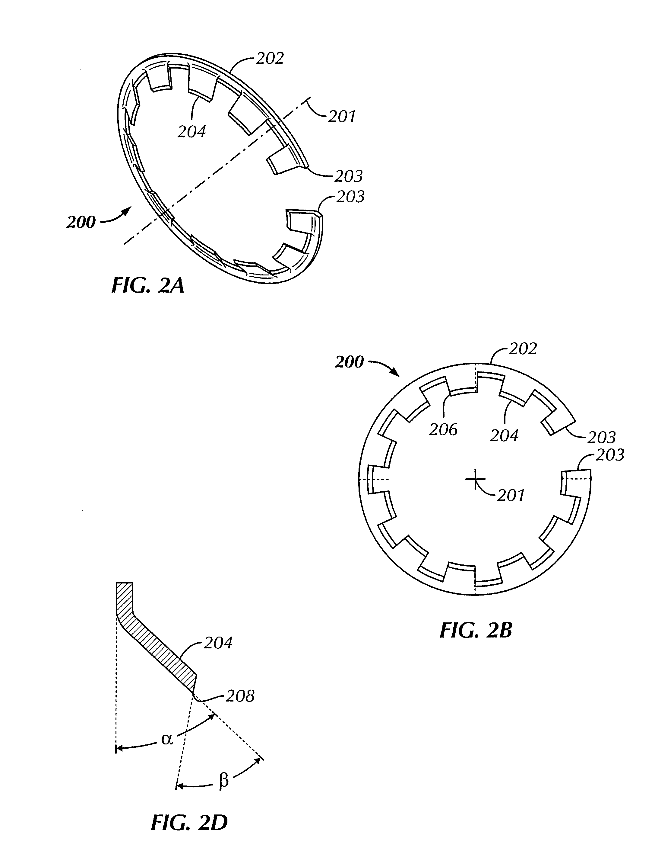
[0019]In one aspect, embodiments disclosed herein relate to tool-free tubular connectors for joining tubular conduit. More particularly, embodiments disclosed herein relate to connectors having an interior retainer ring for securing tubular conduit and related methods. Referring to FIG. 1A, a cross-sectional view of a tool-free connector 100 in accordance with one or more embodiments of the present disclosure is shown. The connector 100 includes a connector body 102 having a central bore 104 and a central axis 101 therethrough. Further, the connector body 102 may have a flange 106 formed on an end thereof.

[0020]The connector body 102 may be comprised of an electrically conductive material (e.g., metallic materials). In certain embodiments, the connector body 102 may be comprised of steel. In alternate embodiments, the connector body 102 may be comprised of zinc plated steel. In other embodiments, the connector body 102 may be comprised of a diecast, formed, or machined material, for...


PUM


Abstract

A threadless connector includes a connector body having a central bore therethrough and a retainer ring disposed in an end of the connector body, the retainer ring comprising a plurality of teeth segments, wherein the plurality of teeth segments are configured to be inwardly angled to contact an end of a conduit inserted into the connector body.

Description

BACKGROUND[0001]1. Field of the Disclosure[0002]Embodiments disclosed herein relate generally to tubular connectors. In particular, embodiments disclosed herein relate to tool-free tubular connectors for joining tubular conduit. More particularly, embodiments disclosed herein relate to connectors having an interior retainer ring for securing tubular conduit.[0003]2. Background Art[0004]An electrical conduit is an electrical piping system used for protection and routing of electrical wiring. Electrical conduit may be made of metal, plastic, fiber, or other materials. Flexible conduit is available for special purposes. Electrical Metallic Tubing (“EMT”), sometimes called thin-wall, is commonly used instead of Electrical Rigid Metal Conduit—Steel (“ERMC-S”) or Intermediate Metal Conduit (“IMC”) because EMT is less costly and lighter. However, EMT is not capable of being threaded. Therefore, lengths of conduit may be connected to each other and to equipment with Screw Type or Compressio...

Claims


Application Information

Patent Timeline
Patent Type & Authority Applications(United States)
IPC IPC(8): F16L39/00
CPCF16L37/091
Inventor PETERSEN, SHERIDONPETERS, BARRYTHOMPSON, BRUCE
Owner REPUBLIC CONDUIT INC
Why Eureka
Try Eureka