
Proximity sensing for capacitive touch sensors

a capacitive touch sensor and proximity sensing technology, applied in the field of input devices and processing systems, can solve the problems of substantial space and size constraints, infrared sensors and their supporting circuits increasing manufacturing costs, and separate subsystems for infrared sensors occupying additional space within the electronic system

Active Publication Date: 2012-03-29
SYNAPTICS INC
View PDF5 Cites 160 Cited by
  • Summary
  • Abstract
  • Description
  • Claims
  • Application Information

AI Technical Summary

Benefits of technology

[0008]In another embodiment, a processing system for an input device includes sensor circuitry configured to be communicatively coupled to a proximity sensor electrode and an array of capacitive sensor electrodes having a plurality of transmitter sensor electrodes and a plurality of receiver sensor electrodes. The processing system further includes control logic configured to operate the input device in a first mode by driving a sensing signal on at least one transmitter sensor electrode of the plurality of transmitter sensor electrodes, receiving a resulting signal from at least one receiver sens

Problems solved by technology

One challenge in touch sensor device design is differentiating between deliberate input and incidental contact to the touch sensor device.
However, infrared sensors and their supporting circuitry increase the manufacturing costs and are limited to detecting objects in a pre-defined position relative to the infrared sensor.
Further, a separate subsystem for the infrared sensor may take up additional space within the electronic system which already faces substantial space and size constraints.

Method used


Image

  • Proximity sensing for capacitive touch sensors
  • Proximity sensing for capacitive touch sensors
  • Proximity sensing for capacitive touch sensors

Examples


Embodiment Construction

[0018]The following Detailed Description is merely provided by way of example and not of limitation. Furthermore, there is no intention to be bound by any expressed or implied theory presented in the preceding technical field, background, brief summary or the following detailed description.

[0019]Various embodiments of the present invention provide input devices and methods that facilitate improved usability of a touch screen device.

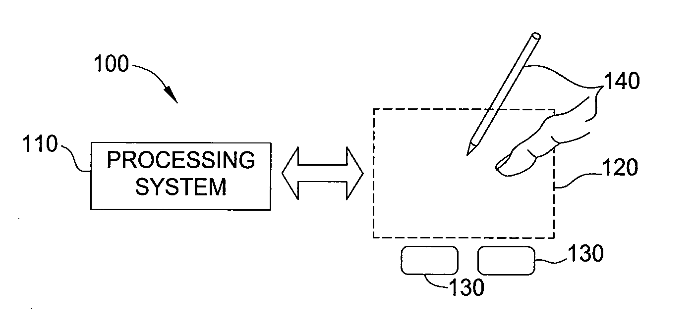
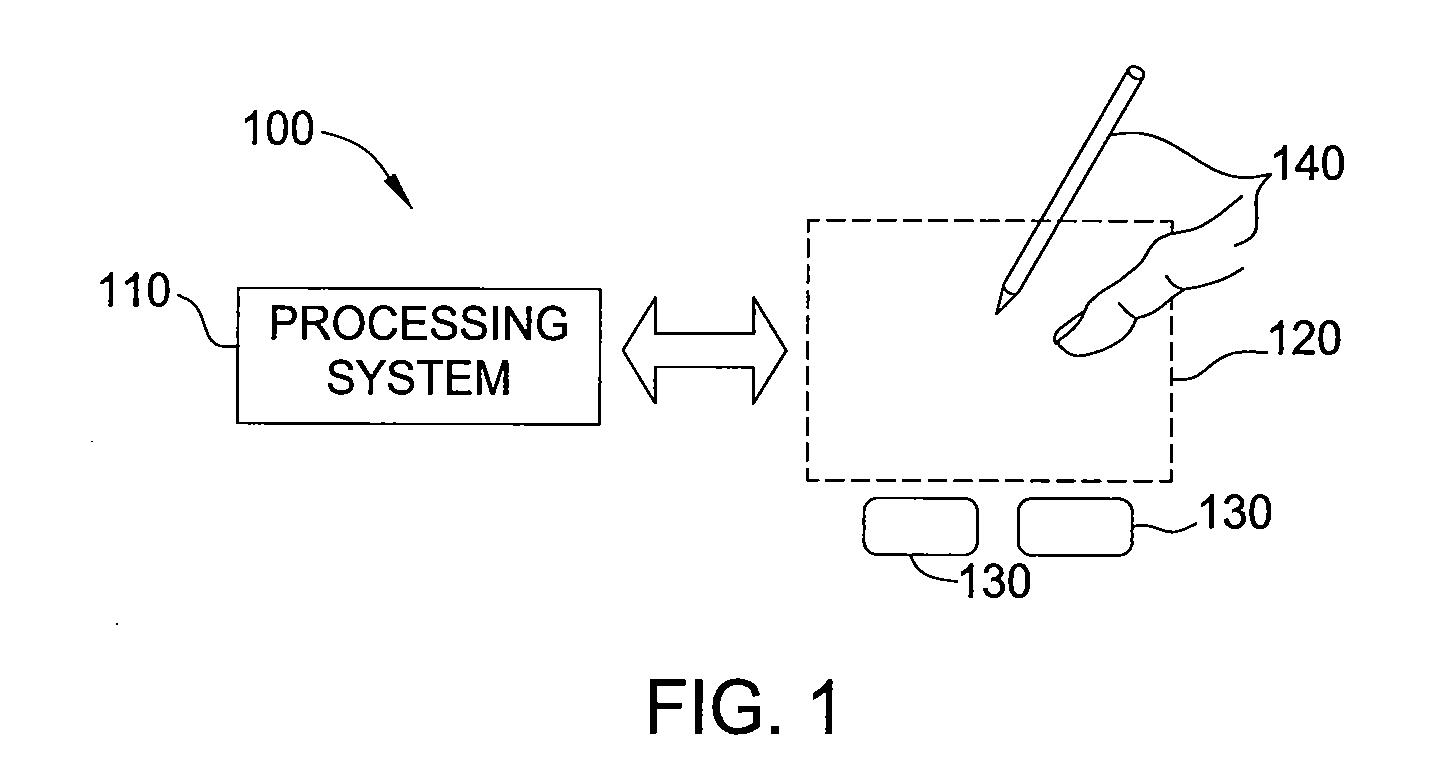
[0020]FIG. 1 is a schematic diagram of an exemplary input device 100, in accordance with embodiments of the invention. The input device 100 may be configured to provide input to an electronic system (not shown). As used in this document, the term “electronic system” (or “electronic device”) broadly refers to any system capable of electronically processing information. Some non-limiting examples of electronic systems include personal computers of all sizes and shapes, such a desktop computers, laptop computers, notebook computers, tablets, web browsers, e-...


PUM


Abstract

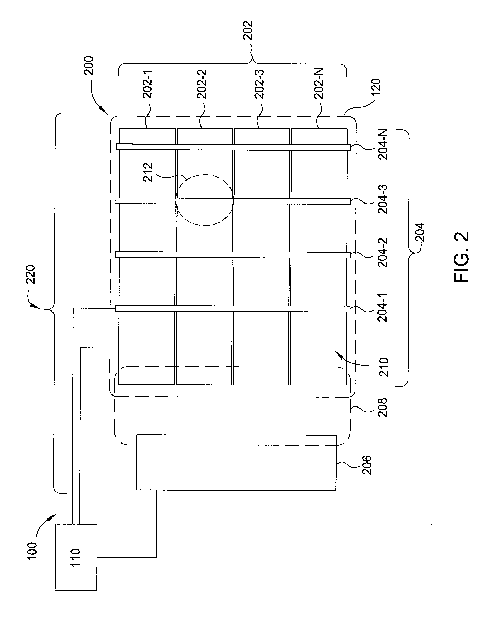
A method and apparatus for operating an input device having an array of capacitive sensor electrodes and a proximity sensor electrode are disclosed herein. The input device includes a processing system communicatively coupled to the array of capacitive sensor electrodes and the proximity sensor electrode and configured to operate in an input mode and a proximity mode. When operating in the input mode, the processing system scans the array of capacitive sensor electrodes to detect input from an object in an active region of the input device. When operating in the proximity mode, the processing system drives a sensing signal on at least one sensor electrode of the array of capacitive sensor electrodes and receives a resulting signal from the proximity sensor electrode. Based on the resulting signal, the processing system generates an indication of an object presence in a second sensing region from the resulting signal.

Description

FIELD OF INVENTION[0001]Embodiments of the present invention generally relate to an input device, processing system, and method for proximity sensing utilizing capacitive touch sensors.BACKGROUND[0002]Touch sensor devices (also commonly called touch pads or touch screens) are widely used in a variety of electronic systems. A touch sensor device is typically a sensitive surface that uses capacitive, resistive, inductive, optical, acoustic or other technology to determine the presence, location and or motion of one or more fingers, styli, and / or other objects. The touch sensor device, together with a finger or other object provides an input to the electronic system. For example, touch sensor devices are used as input devices for computers, such as notebook computers.[0003]Touch sensor devices are also used in smaller devices, such as personal digital assistants (PDAs) and communication devices such as wireless telephones and text messaging devices. Increasingly, touch sensor devices a...

Claims


Application Information

Patent Timeline
IPC IPC(8): G06F3/044H04W4/24
CPCG06F3/044G06F2203/04108H04L41/0893H04L41/5003H04W4/26H04M15/00H04M15/58H04M2215/0188H04W4/24H04L41/5025G06F3/0445G06F3/0446
Inventor HOCH, DAVID
Owner SYNAPTICS INC
Learn More