
Safe Exposed Conductor Power Distribution System

a safety protection device and power distribution system technology, applied in emergency protective circuit arrangements, circuit arrangements, electrical equipment, etc., can solve problems such as hardware failure, low line resistance, etc., and achieve the effect of safe energy transfer

Inactive Publication Date: 2012-03-29
VOLTSERVER INC
View PDF17 Cites 53 Cited by
  • Summary
  • Abstract
  • Description
  • Claims
  • Application Information

AI Technical Summary

Benefits of technology

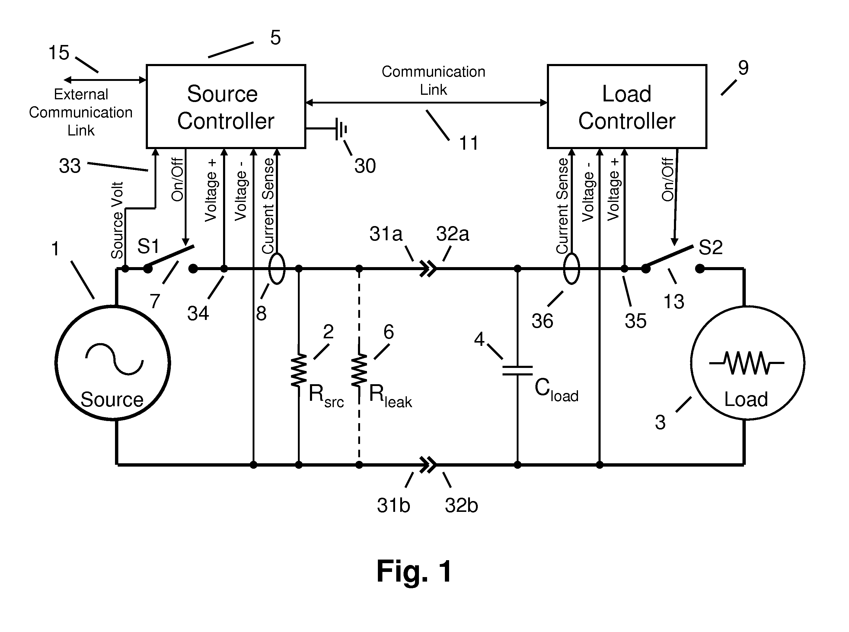
[0035]The present invention provides a novel power distribution system that can safely transfer energy from a source

Problems solved by technology

A line resistance that is lower than expected is an indication of a hardware failure.

Method used


Image

  • Safe Exposed Conductor Power Distribution System
  • Safe Exposed Conductor Power Distribution System
  • Safe Exposed Conductor Power Distribution System

Examples


Embodiment Construction

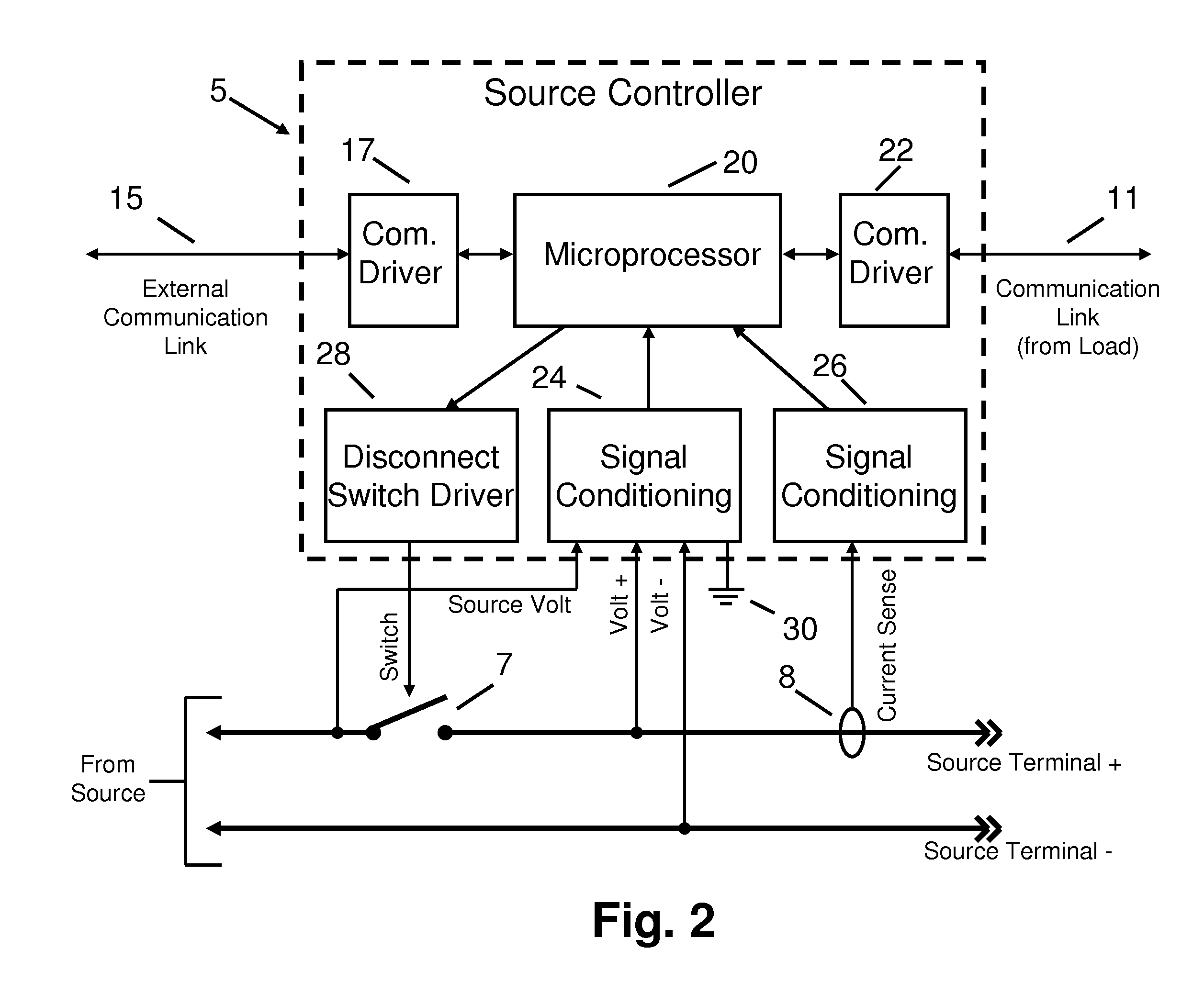
[0022]There are a number of industry standard methods for constructing the S1 and S2 disconnect switches 7, 13 of FIG. 1. In the preferred embodiment a different arrangement is employed depending on if the system is distributing DC or AC power. For DC power distribution, DC disconnect switch arrangement 37 of FIG. 6A is preferred. In this arrangement electrical current is blocked in the minus to positive direction by blocking diode 39. Current flow in the positive to negative direction is controlled by internal switch 38 according to the application of control signal 40. The transistor type used for internal switch 38 is chosen based on the electrical voltage and current requirements. Industry standard transistors would include FETs, IGBTs or IGCTs. The electrical implementation of control signal 40 for controlling the conduction of internal switch 38 is dependent on the type of transistor but is well known to those skilled in the art of power electronics.

[0023]For AC power distribu...


PUM


Abstract

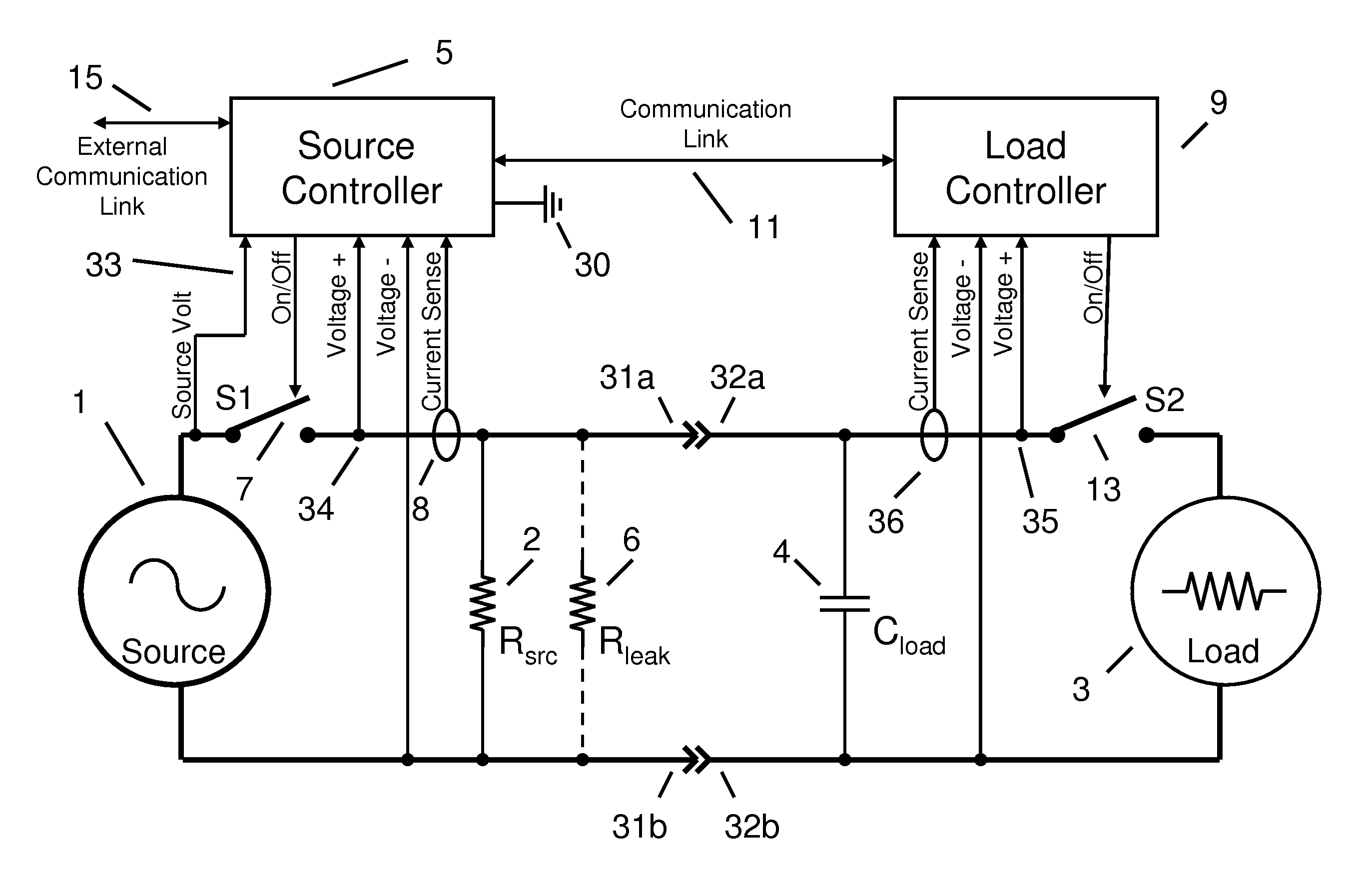
A power distribution system that can detect an unsafe fault condition where an individual or object has come in contact with the power conductors. A block diagram of the present invention is shown in FIG. 1. The power distribution system regulates the transfer of energy from a source 1 to a load 3. Periodically, source controller 5 opens S1 disconnect switch 7 and load controller 9 opens S2 disconnect switch 13. A capacitor 4 represents that capacitance across the load terminals. If the capacitor discharges at a rate higher or lower than predetermined values after S1 and S2 are opened, then a fault condition is registered and S1 and S2 will not be commanded to return to a closed position, thus isolating the fault from both the source and load.

Description

CLAIM OF PRIORITY[0001]This application claims priority to U.S. Ser. No 61 / 255,463 entitled “Safe Exposed Conductor Power Distribution System”, filed on Oct. 27, 2009, naming Stephen Eaves of Charlestown, R.I. as inventor, the contents of which are herein incorporated by reference in their entirety.FIELD OF INVENTION[0002]This invention relates to power distribution system safety protection devices. More specifically, power distribution systems with electronic monitoring to detect and disconnect power in the event of an electrical fault or safety hazard; particularly where an individual has come in contact with exposed conductors. This invention is applicable to general power distribution, or more specifically electric vehicle charging systems, electric railway vehicle power distribution or energized roadways for electric vehicles.BACKGROUND[0003]In a typical power distribution application, power from a central source is distributed through a number of branch circuits to a load devi...

Claims


Application Information

Patent Timeline
IPC IPC(8): H02H3/02
CPCH02H3/40H02H7/263H02H3/44
Inventor EAVES, STEPHEN SPENCER
Owner VOLTSERVER INC
Learn More