Sealing System for Centrifugal Pumps

Active Publication Date: 2012-03-29
KSB AG
8 Cites 0 Cited by

AI-Extracted Technical Summary

Problems solved by technology

When hot fluids are being delivered, the return line for the relief water represents an additional source of heat, which can have a negative effect o...

Benefits of technology

[0020]In order to dissipate the heat as quickly as possible from the seal housing, there is preferably a flow of air through the ducts. It has proven advantageous to position a fan impeller on a rotating part, in particular a coupling of the pump, said impeller delivering an air flow through the ducts. To ensure that the air also flows...

Abstract

A centrifugal pump for delivering hot fluids, having a contacting shaft seal, a seal housing (13) for the shaft seal (14), and a return line (8) for a partial flow of the delivered fluid, in which no delivered fluid is discharged out of the seal housing (13); a separate housing cover (9) is disposed between the seal housing (13) and the pump housing (1); there is a contact surface which minimizes heat transfer between the seal housing (13) and the housing cover (9);, and the return line (8) is connected to the housing cover (9) and/or to the pump housing (1).

Application Domain

Technology Topic

Image

  • Sealing System for Centrifugal Pumps
  • Sealing System for Centrifugal Pumps
  • Sealing System for Centrifugal Pumps

Examples

  • Experimental program(1)

Example

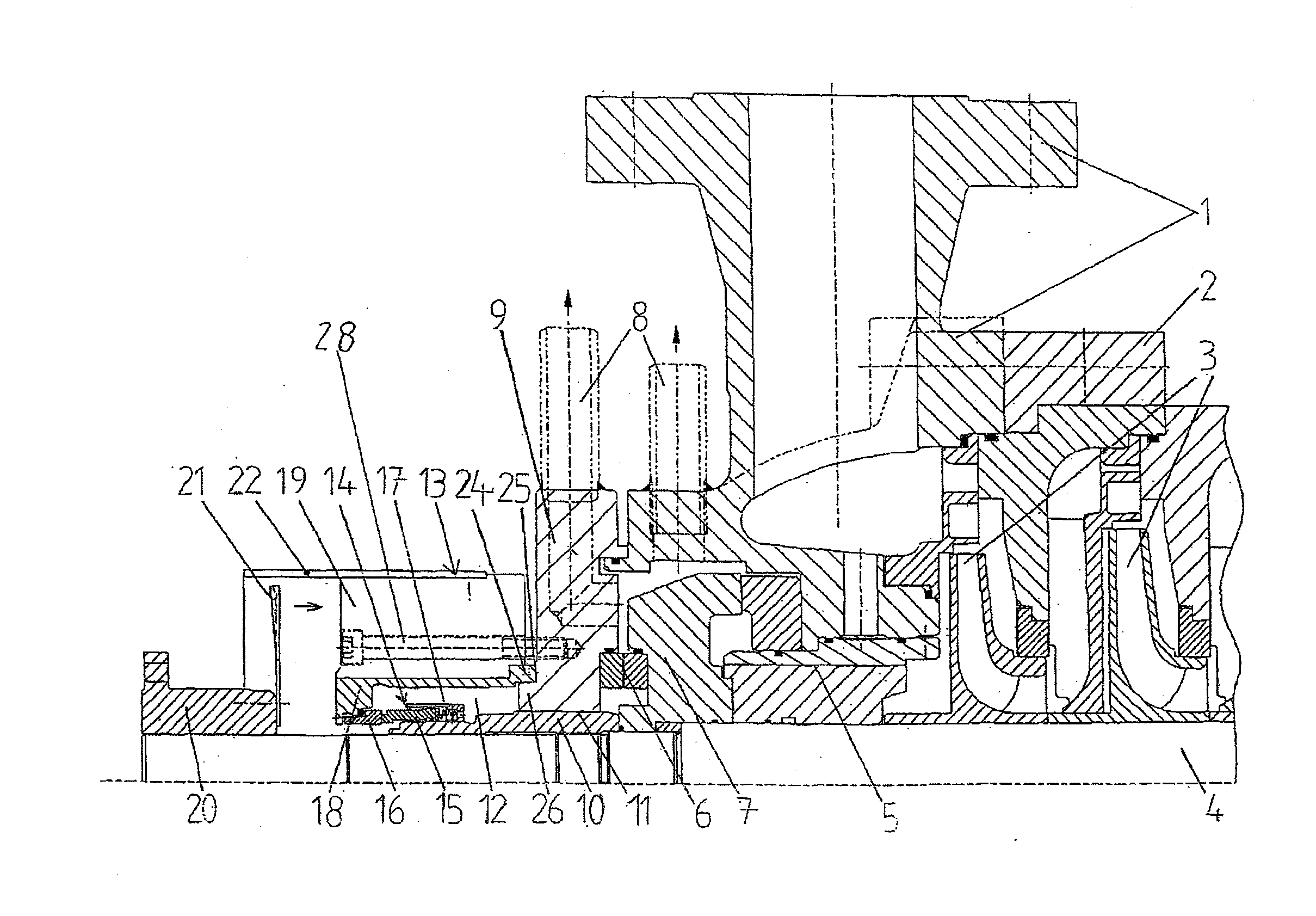
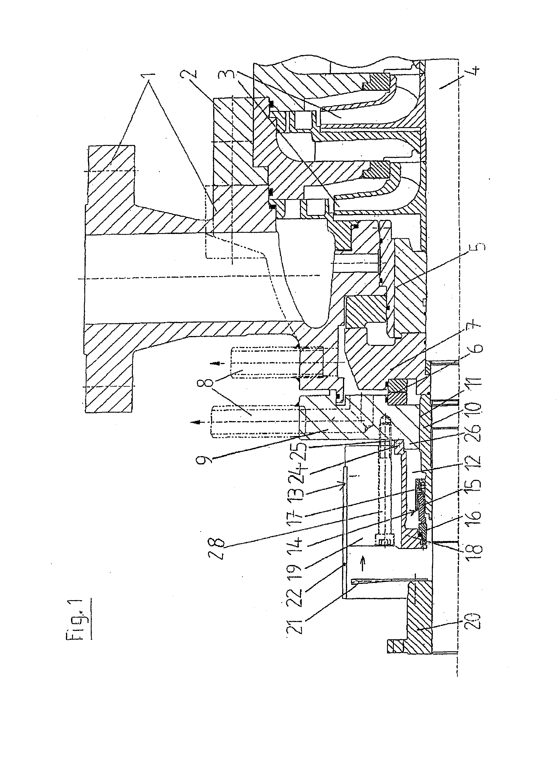
[0024]FIG. 1 shows a section of a multi-stage centrifugal pump. The centrifugal pump comprises a pressure housing 1 and a stage housing 2. The impellers 3 are mounted on a shaft 4 and together form the rotor. This rotor is supported by radial bearings 5 and axial bearings 6. An axial thrust of the rotor is taken by a relief device 7. In principle, there are two different ways in which relief water flowing out from the latter can be discharged according to the invention. In the case of the first way, a return line 8 for the relief water runs through the pressure housing 1. In the second way, the return line 8 runs through the housing cover 9 which closes the pressure housing 1. The housing cover 9 adjoins the pressure housing 1 in a sealing manner.
[0025]An axial gap 11 is formed between the housing cover 9 and a shaft protection sleeve 10. The axial gap 11 acts as a restrictor for the delivered fluid in the pump housing and prevents relatively large quantities of delivered fluid from flowing into the chamber 12 of the seal housing 13.
[0026]A mechanical seal 14 is disposed within the seal housing 13. Mechanical seals belong to the category of contacting seals. The mechanical seal 14 consists of two low-wear rings. The sliding ring 15 revolves with the shaft 4 or with the shaft protection sleeve 10, while the mating ring 16 rests in a fixed manner on the seal housing 13. The sliding ring 15 and the mating ring 16 are pressed against each other by a spring 17.
[0027]The seal housing 13 is comprised of the inner part 18, which surrounds the mechanical seal 14, and an outer part 19. The outer part 19 is a bronze body. The inner part 18 is embodied as a stainless steel sleeve, which is shrunk-fit into the outer part 19. The stainless steel sleeve 18 is required to ensure corrosion resistance, while the bronze body 19 serves primarily for heat dissipation.
[0028]A fan impeller 21, which blows air over the seal housing 13, is mounted on a coupling 20 which connects the pump to a drive. The air flows through ducts situated between ribs on the outer part and dissipates the heat from the seal housing 13. For better guidance of the air, the outer part 19 of the seal housing 13 is surrounded by a baffle plate 22.
[0029]The axial ducts 23 in the outer part 19 of the seal housing 13 can be seen in the perspective view shown in FIG. 2. The ducts 23 are open toward the outer lateral surface of the seal housing 13. The fan impeller 21 blows air through the ducts 23. A baffle plate 27, which is not shown here for reasons of clarity (cf. FIG. 1), is made somewhat shorter than the length of the ducts 23. It rests against an offset 27 and improves guidance of the air in the ducts 23. Between the baffle plate ends at the offset 27 and the housing cover 9, the ducts are of open design and serve as an outlet opening for the cooling air flow. The baffle plate 22 ensures a forced flow of air through the inner areas of the ducts 23.
[0030]The seal housing 13 has a projection 24, which is formed by the inner part 18 of the seal housing 13. The surface 25 of the projection 24, which runs around vertically, serves as a contact surface of the seal housing 13 at the housing cover 9. To center the seal housing 13 relative to the pump housing, the shaft 4 and the pressure cover 9, the inner part 18 in this example is pushed with its projection 24 onto a smaller-diameter projection 26 of the housing cover 9. Connecting means 28 are used to hold the seal housing 13 and the pressure cover 9 together. The projection 26 of the housing cover 9 projects into the seal housing 13.
[0031]The foregoing description and examples have been set forth merely to illustrate the invention and are not intended to be limiting. Since modifications of the described embodiments incorporating the spirit and substance of the invention may occur to persons skilled in the art, the invention should be construed broadly to include all variations within the scope of the appended claims and equivalents thereof.

PUM

no PUM

Description & Claims & Application Information

We can also present the details of the Description, Claims and Application information to help users get a comprehensive understanding of the technical details of the patent, such as background art, summary of invention, brief description of drawings, description of embodiments, and other original content. On the other hand, users can also determine the specific scope of protection of the technology through the list of claims; as well as understand the changes in the life cycle of the technology with the presentation of the patent timeline. Login to view more.

Similar technology patents

Heat dissipating system using fans

Owner:MINGSHUO COMP (SUZHOU) CO LTD +1

Shield casing with heat sink for electric circuits

InactiveUS20050018411A1Dissipate heatGood shieldingShielding materialsRack/frame constructionEngineeringHeat spreader
Owner:THOMSON LICENSING SA

Lighting apparatus

InactiveUS20100246188A1Dissipate heatLess wattage consumeIncadescent body mountings/supportIncadescent screens/filtersPhysicsEllipse
Owner:WALTON RANDAL

Helmet and headwear misting system

InactiveUS6938831B1Quickly and effectively cool downDissipate heatBreathing masksDe-icing equipmentsWater reservoirEngineering
Owner:BROWN GARY

Classification and recommendation of technical efficacy words

Why Eureka
Try Eureka