

Methods and apparatus for recycling glass products using submerged combustion
a technology of submerged combustion and glass products, which is applied in the direction of lighting and heating apparatus, furnaces, charge manipulation, etc., can solve the problems of large amount of fiber cost not in the material, the size of glass fibers, and the inability of submerged combustion burners to recycle or reclamate glass mat products. to achieve the effect of reducing or eliminating the need to shred or crush
- Summary
- Abstract
- Description
- Claims
- Application Information
AI Technical Summary
Benefits of technology
Problems solved by technology
Method used
Image

Examples
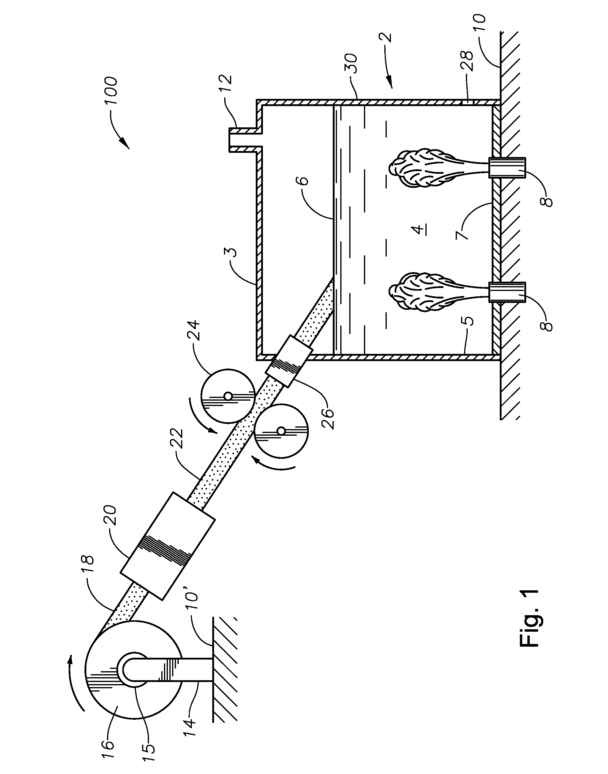
embodiment 100
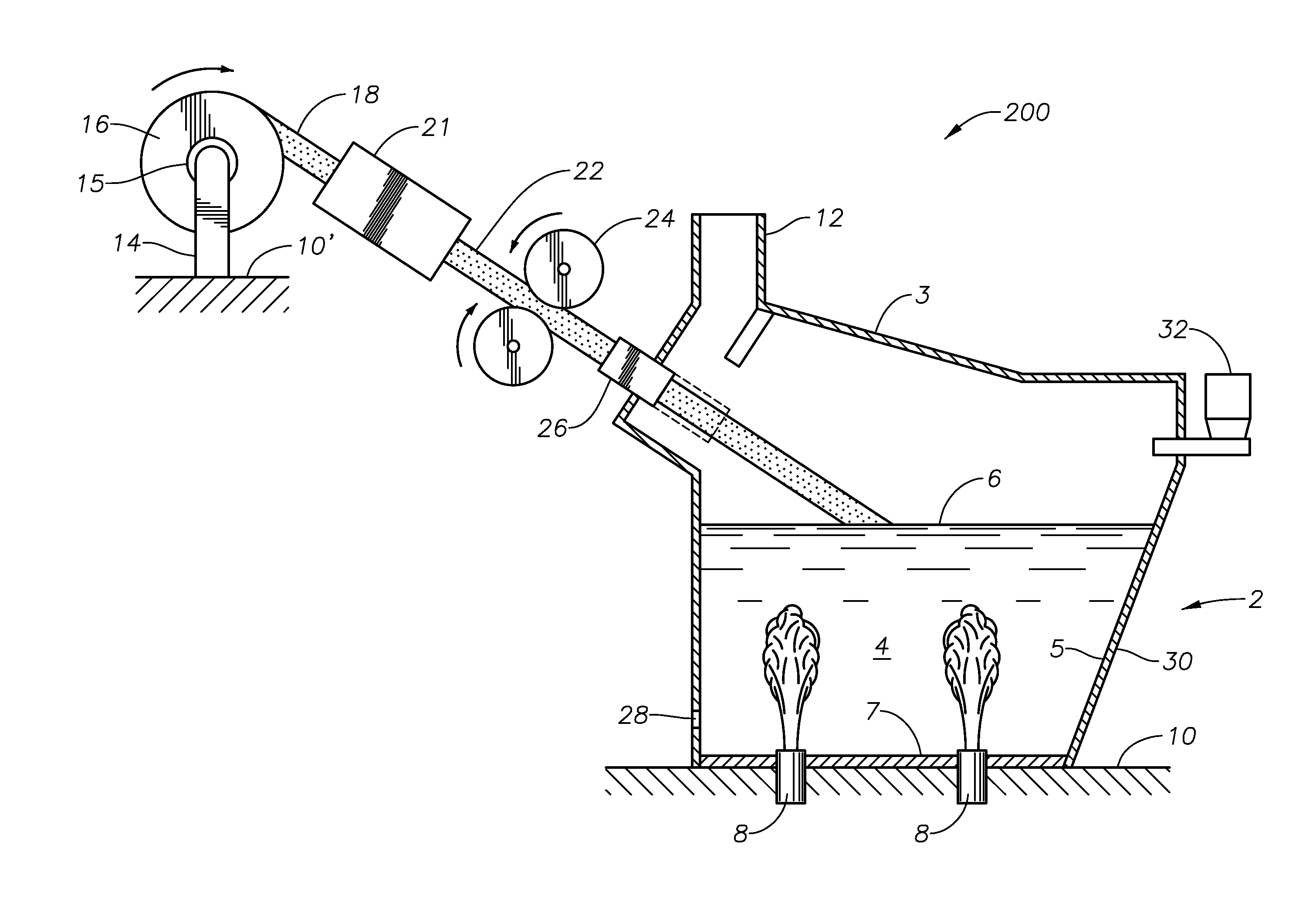
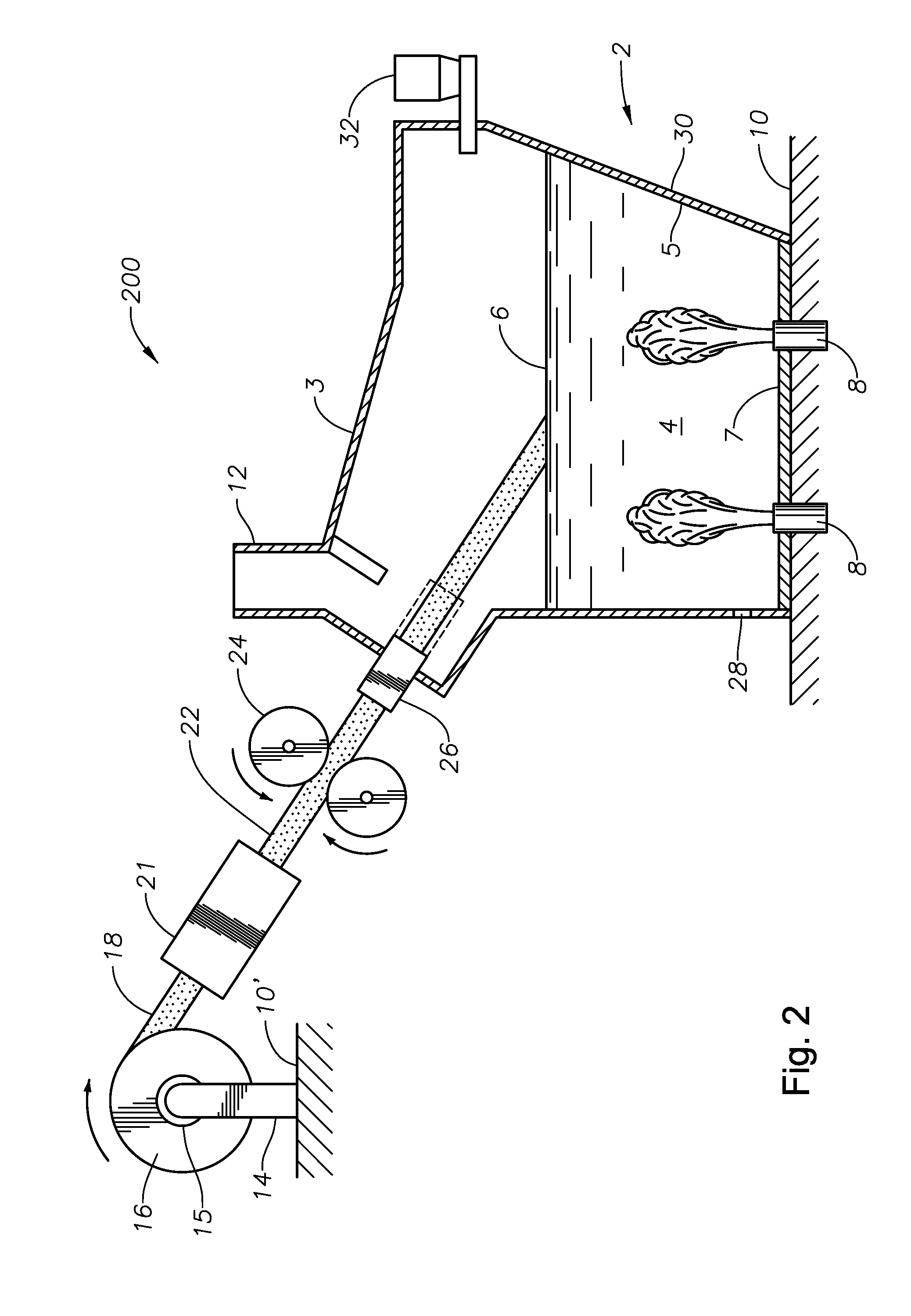
[0046]Embodiment 100 of FIG. 1 comprises a melter 2, which may be any of the currently known submerged combustion melter designs as exemplified in the patent documents previously incorporated hereby reference in the Background of the present disclosure, or may be one of those described in assignee's currently pending patent application Ser. No. 12 / 817,754, filed Jun. 17, 2010, incorporated herein by reference. Melter 2 includes a roof 3, side walls 5, a floor 7, one or more submerged combustion burners 8, an exhaust chute 12, one or more molten glass outlets 28 (only one being illustrated), and fluid-cooled panels 30 comprising some or all of side walls 5. Molten glass 4 is sometimes referred to herein simply as the “melt”, and has a level 6 in melter 2. Melter 2 is typically supported on a plant floor 10.
[0047]In accordance with the present disclosure, first embodiment 100 comprises one or more roll stands 14 (only one being illustrated), which in turn supports one or more rolls 16...
embodiment 80
[0074]FIGS. 4-8 illustrate non-limiting examples of slots useful in apparatus and methods of this disclosure. FIG. 4 illustrates a perspective view of embodiment 80, having a single door or panel 82 which swings open vertically away from melter 2 when it is desired to feed a non-woven 22 into melter 2 for recycling. Door or panel 82 is secured to melter 2 by a hinge 84 which ruins along the bottom edge of door 82, and handles 86, 87 are provided in this embodiment to allow personnel to open and close door 82. Alternatively, or in addition, a mechanical opening and closing mechanism may be provided, such as that discussed in reference to FIG. 7, or equivalent thereof.
[0075]FIG. 5 illustrates a perspective view of another embodiment 90 within this disclosure, this embodiment comprising a pair of horizontally opening doors 92, 94, also featuring hinged connections 93, 95, connecting the doors to melter 2, respectively.
embodiment 110
[0076]FIG. 6 illustrates a side elevation view of an embodiment 110 of a vertical sliding door or panel 112 which may function as a slot in accordance with the present disclosure, where panel 112 is integral with a fluid-cooled wall 30 of melter 2. Sliding door or panel 112 may be held open or closed at a variety of vertical positions, for example using a locking device, clamp or similar mechanism 114. This would allow nonwovens of various thicknesses to be processed. Sliding door or panel 112 may itself be fluid-cooled.
[0077]FIG. 7 illustrates a perspective view of yet another embodiment 120 of a slot useful in the apparatus and methods of this disclosure. Embodiment 120 comprises a vertically sliding door or panel 122, and a horizontally sliding door or panel 124. Vertical door or panel 122 slides in vertical guides 126, 128, while horizontal door or panel 124 slides in guides 129. In order to open and close, or adjust the height of vertical door or panel 122, handles 130, 132 may...
PUM
| Property | Measurement | Unit |
|---|---|---|
| Pressure | aaaaa | aaaaa |
| Feed rate | aaaaa | aaaaa |
| Width | aaaaa | aaaaa |
Abstract
Description
Claims
Application Information