Retainers for transcatheter heart valve delivery systems

a technology of transcatheter heart valve and stent, applied in the field of prosthetic heart valve replacement, can solve the problems of stent strut damage or deformation, difficulty in releasing the valve, and inconvenient use of conventional delivery devices, systems and methods,

Active Publication Date: 2012-03-29
ST JUDE MEDICAL LLC
View PDF18 Cites 69 Cited by
  • Summary
  • Abstract
  • Description
  • Claims
  • Application Information

AI Technical Summary

Benefits of technology

[0024]The acceptance may include at least one protuberance defining a narrowed neck in the acceptance. The method may further include resheathing the valve by sliding the sheath in a second one of the longitudinal directions relative to the valve opposite the first longitudinal direction, whereby an engagement of the retention member with the protuberance keeps the retention member positioned in the acceptance during the resheathing.

Problems solved by technology

Despite the various improvements that have been made to the collapsible prosthetic heart valve delivery process, conventional delivery devices, systems, and methods suffer from some shortcomings.
During deployment of the self-expanding valve into the desired area (e.g., the aortic valve annulus), the high frictional force produced during unsheathing of the valve may cause high axial forces to be applied directly to the two or three retention members, which may damage or deform the stent struts that support the retention members.
Furthermore, the delivery process may cause the stent to become twisted relative to the retainer portion of the catheter, which may make it difficult to release the valve because the stent retention members may catch on the retainer during deployment.

Method used


Image

  • Retainers for transcatheter heart valve delivery systems
  • Retainers for transcatheter heart valve delivery systems
  • Retainers for transcatheter heart valve delivery systems

Examples


first embodiment

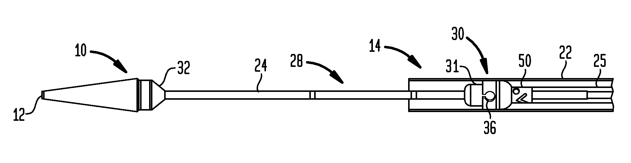
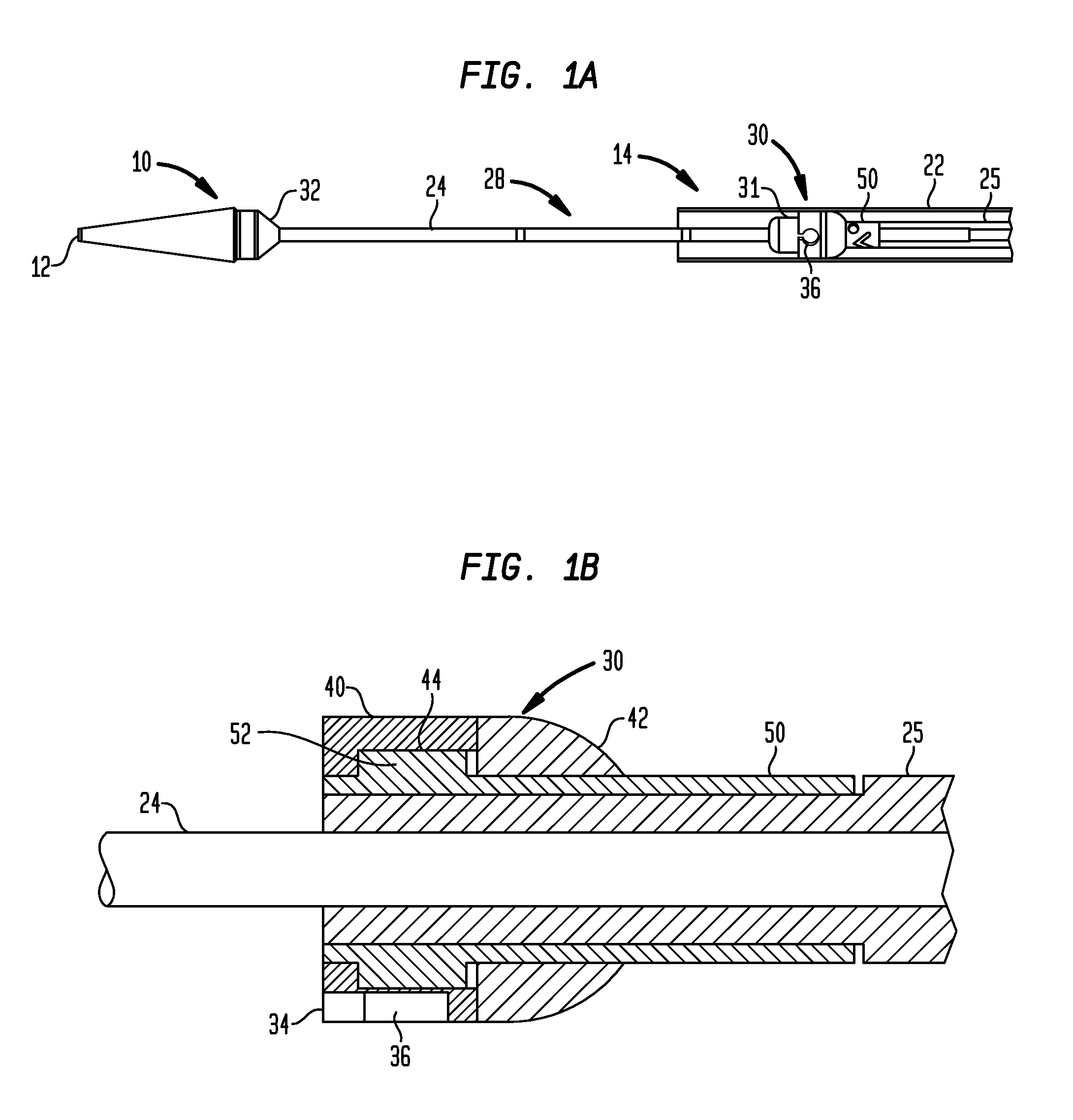
[0043]Referring now to FIG. 1A to illustrate the structure and function of the present invention, a delivery device 10 has a distal tip 12 and a catheter assembly 14 extending from the distal tip 12 to a proximal end (not shown) that includes a handle (not shown) for a user to control the delivery device 10. The delivery device 10 is an exemplary transfemoral delivery device for a collapsible prosthetic heart valve.

[0044]Although the delivery device 10 is a transfemoral delivery device, the inventive retainers shown and described in this application may be configured to be used with a transapical delivery device (e.g., the device 10′ shown in FIGS. 2A and 2B) or other types of tube-like delivery devices for collapsible stents.

[0045]The catheter assembly 14 includes a sheath 22 extending from the handle towards the distal tip 12, a hollow inner shaft 24 located inside of the sheath 22 and extending from the handle to the distal tip 12, and a valve receiving compartment 28 configured ...

second embodiment

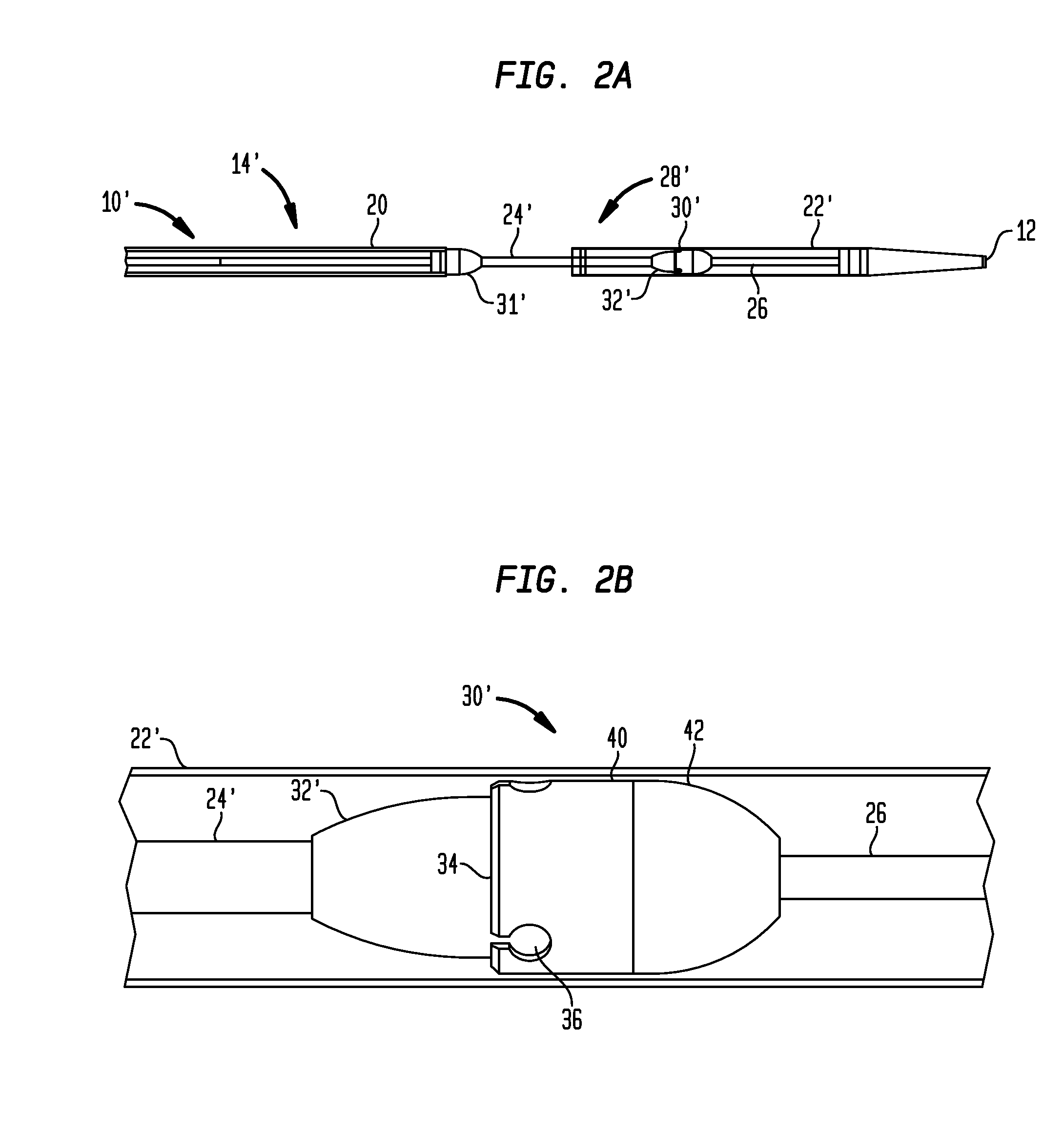
[0056]Referring to FIG. 2A, a delivery device 10′ has a distal tip 12 and a catheter assembly 14′ extending from the distal tip 12 to a proximal end (not shown) that includes a handle (not shown) for a user to control the delivery device 10′. The delivery device 10′ is an exemplary transapical delivery device for a collapsible prosthetic heart valve.

[0057]The catheter assembly 14′ includes a proximal sheath extending from the handle towards the distal tip 12, a distal sheath 22′ extending from the distal tip 12 towards the handle, a hollow tube 26 that extends slidably from the proximal end through the proximal sheath 20 and attaches to the distal sheath 22′ at the distal tip 12 of the delivery device 10′, and a valve receiving compartment 28′ configured to receive a prosthetic valve for delivery inside of a patient.

[0058]The valve receiving compartment 28′ is configured to receive a collapsible prosthetic heart valve. The valve receiving compartment 28′ includes a proximal conical ...


PUM


Abstract

A delivery device for an implantable medical device having at least one retention member at an end thereof includes a shaft extending in a longitudinal direction, an elongated sheath surrounding a longitudinal portion of the shaft, a compartment defined inside of the sheath and adapted to receive the medical device in an assembled condition, a retainer positioned at one end of the compartment, and at least one acceptance in the retainer adapted to receive the retention member of the medical device in the assembled condition. The sheath is slidable relative to the shaft in the longitudinal direction to uncover and deploy the medical device. The retainer may be rotatable relative to the shaft to reduce torsional forces in the medical device during delivery and deployment. The retainer may have at least one recess facing the compartment for receiving a strut at an end of a stent of the medical device.

Description

CROSS-REFERENCE TO RELATED APPLICATIONS[0001]This application claims the benefit of the filing date of U.S. Provisional Patent Application No. 61 / 364,453 filed Jul. 15, 2010, the disclosure of which is hereby incorporated herein by reference.BACKGROUND OF THE INVENTION[0002]The present invention is related to prosthetic heart valve replacement, and more particularly to devices, systems, and methods for transcatheter delivery of collapsible prosthetic heart valves.[0003]Prosthetic heart valves that are collapsible to a relatively small circumferential size can be delivered into a patient less invasively than valves that are not collapsible. For example, a collapsible valve may be delivered into a patient via a tube-like delivery apparatus such as a catheter, a trocar, a laparoscopic instrument, or the like. This collapsibility can avoid the need for a more invasive procedure such as full open-chest, open-heart surgery.[0004]Collapsible prosthetic heart valves typically take the form ...

Claims


Application Information

Patent Timeline
Patent Type & Authority Applications(United States)
IPC IPC(8): A61F2/24
CPCA61F2/2436A61F2/962A61F2002/9665A61F2002/9522A61F2/966A61F2/9522
Inventor WANG, HUISUNGLAZIER, VALERIE J.GRAFOV, ALEX
Owner ST JUDE MEDICAL LLC
Why Eureka
Try Eureka