Switch supervision device, control system and control method

a supervision device and switch technology, applied in the direction of electric controllers, instruments, ignition automatic control, etc., can solve the problems of increasing the manufacturing cost of the control unit, undetectable signal produced in the onboard battery, wasteful consumption of the electric power of the onboard battery by the control unit, etc., to reduce the increase of the manufacturing cost of the switch supervisory device and suppress the consumption of electric power. , the effect of reducing the increase of the manufacturing cos

Active Publication Date: 2012-03-29
DENSO CORP
View PDF15 Cites 5 Cited by
  • Summary
  • Abstract
  • Description
  • Claims
  • Application Information

AI Technical Summary

Benefits of technology

[0009]An object of the present invention is to provide, with due consideration to the drawbacks of the conventional electronic control unit, a switch supervisory device, connected with an object section of an instruction path connecting a control unit for controlling a controlled object and a switch for setting the instruction path in a conductive state to send an instruction signal to the control unit and setting the instruction path in a non-conductive state, which suppresses electric power wastefully consumed in the controlled object while reducing the increase of the manufacturing cost of the switch supervisory device.

Problems solved by technology

However, this current supply unit increases the manufacturing cost of the control unit.
Therefore, when the switch is set in the off state so as to disconnect the signal line from the ground, a signal produced in the onboard battery undesirably goes into the microcomputer through the signal line.
Because this signal acts as a dark current, the control unit wastefully consumes electric power of the onboard battery.
Therefore, a constitutional component (e.g., a timer) for setting the sending timing so as to check the sending of the input signal in synchronization with the sending timing is undesirably required.
This element increases the manufacturing cost of the control unit.

Method used


Image

  • Switch supervision device, control system and control method
  • Switch supervision device, control system and control method
  • Switch supervision device, control system and control method

Examples


embodiment

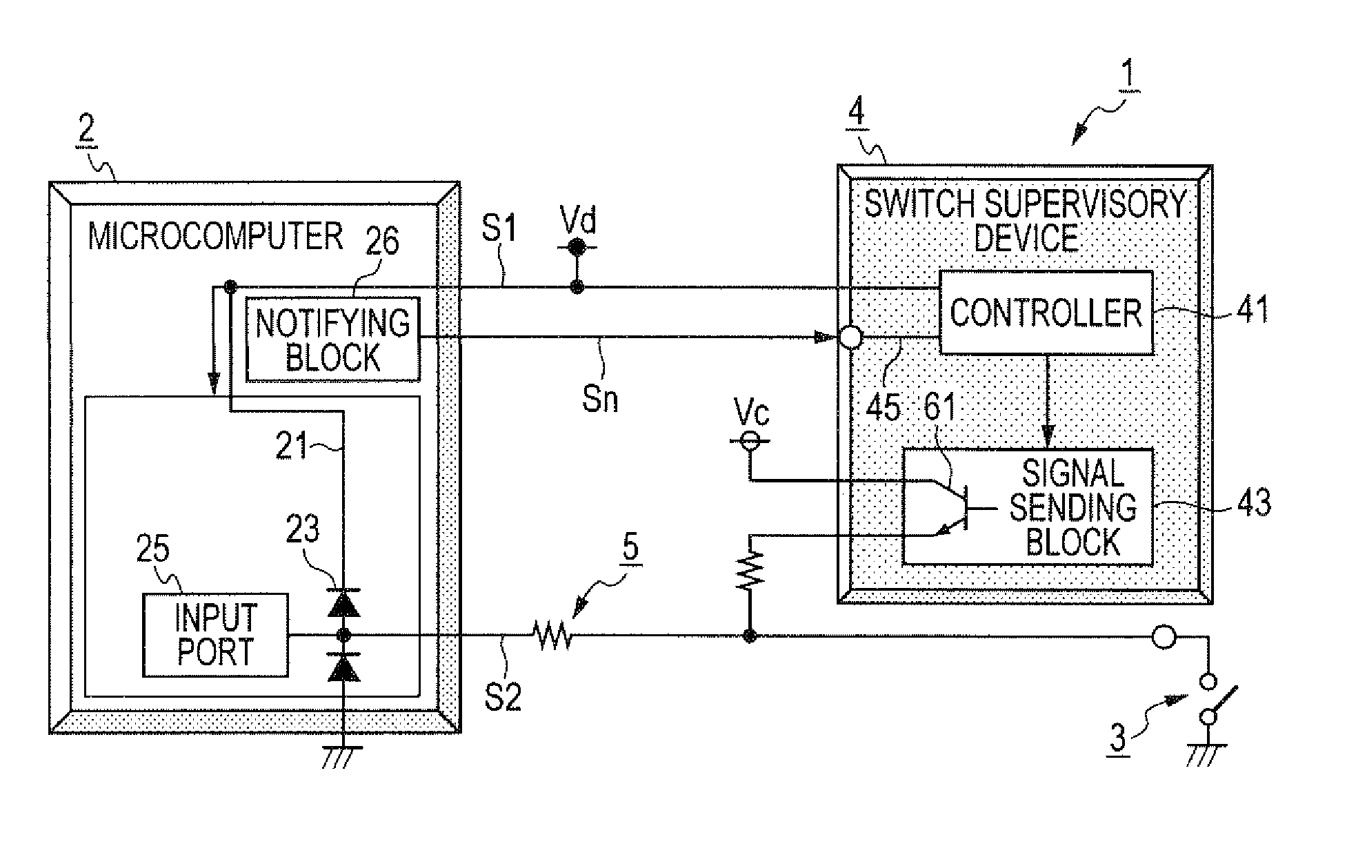
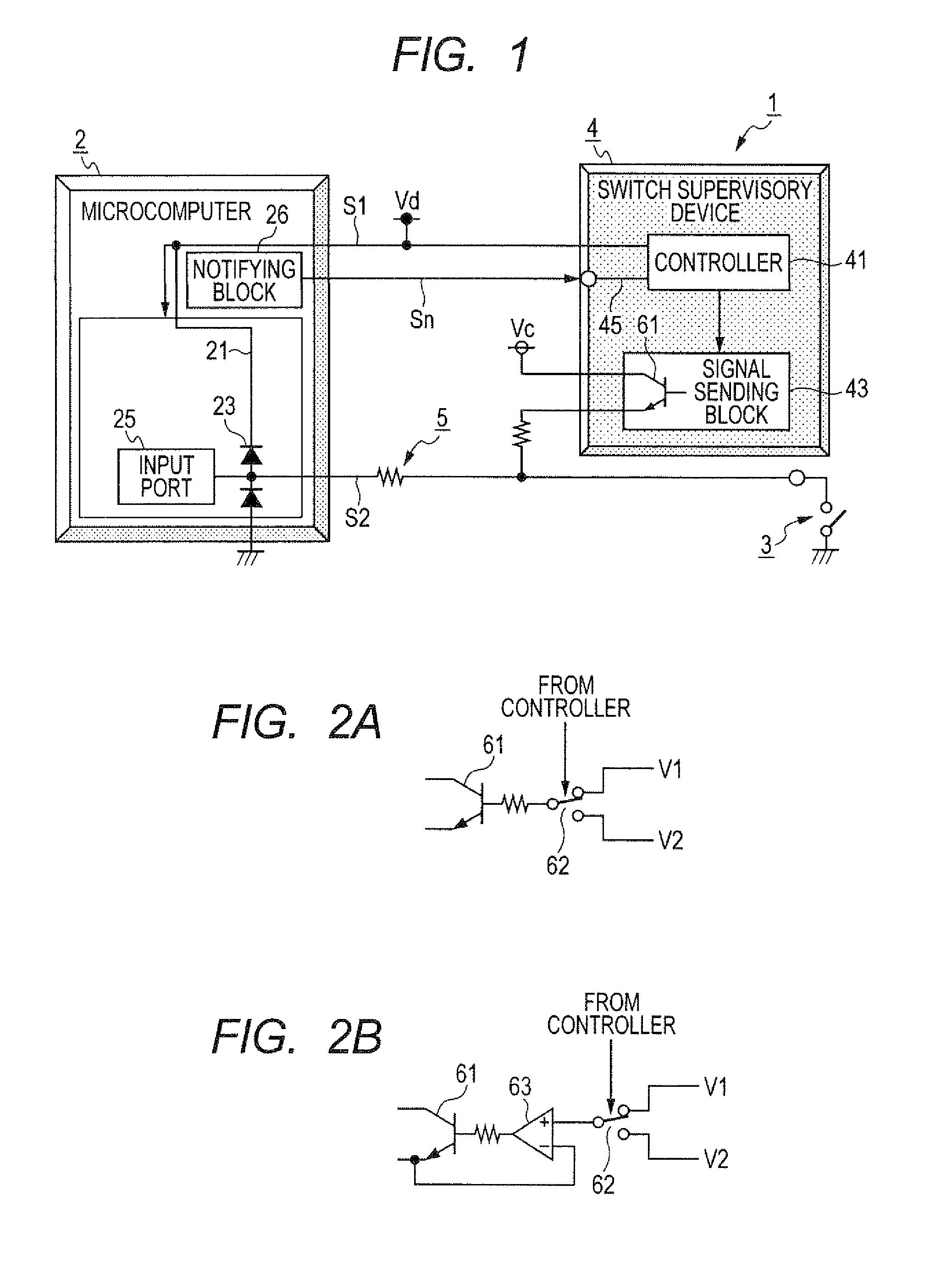
[0027]FIG. 1 is a block diagram showing the structure of a control system according to this embodiment. As shown in FIG. 1, a control system 1 mounted on a vehicle has a microcomputer (i.e., a control unit) 2 for controlling a controlled object (not shown) to operate the vehicle, a switch 3 that is turned on to set an instruction path (i.e., a signal line) in a conductive state and is turned off to set the instruction path in a non-conductive state, and a switch supervisory device 4 connected with an object section of an instruction path.

[0028]The system 1 further has a current-carrying power source Vc, a driving power source Vd and a limiting resistor 5 located in the instruction path to limit the sending of a signal passing through the instruction path. An onboard battery of the vehicle is used as the power source Vc.

[0029]The instruction path extends from the driving power source Vd to the ground through the microcomputer 2 and the switch 3. The instruction path has a high side s...


PUM


Abstract

A control system has an instruction path of which an object section connects a microcomputer, a switch and a switch supervisory device with one another. The switch sets the path in conductive or non-conductive state on the low side of the microcomputer. An instruction signal is sent to the microcomputer through the conductive path to set the microcomputer in an operation state. When the device judges based on the operation state of the microcomputer that the switch has set the path in a conductive state, the device sends a first signal of first voltage, causing the signal to have current strength equal to or higher than predetermined value in the path, to the object section. When the device judges that the switch has set the path in a non-conductive state, the device sends a second signal of second voltage lower than first voltage to the object section.

Description

CROSS-REFERENCE TO RELATED APPLICATION[0001]This application is based upon and claims the benefit of priority of the prior Japanese Patent Application 2010-214159 filed on Sep. 24, 2010, so that the contents of which are incorporated herein by reference.BACKGROUND OF THE INVENTION[0002]1. Field of the Invention[0003]The present invention relates to a switch supervisory device that is connected with an object section of an instruction path connecting a control unit for controlling a controlled object and a switch for setting the instruction path in a conductive state to send an input signal to the control unit and setting the instruction path in a non-conductive state. Further, the present invention relates to a control system having the control block, the switch and the switch supervisory device. Moreover, the present invention relates to a control method for controlling the control system.[0004]2. Description of Related Art[0005]An electronic control unit mounted on a vehicle has s...

Claims


Application Information

Patent Timeline
Patent Type & Authority Applications(United States)
IPC IPC(8): G05B11/01
CPCH01H1/605
Inventor KANAYAMA, MITSUHIRO
Owner DENSO CORP
Why Eureka
Try Eureka