

Parallel link robot, and method of teaching parallel link robot
a robot and parallel link technology, applied in the field of parallel link robots, to achieve the effect of high accuracy
- Summary
- Abstract
- Description
- Claims
- Application Information
AI Technical Summary
Benefits of technology
Problems solved by technology
Method used
Image

Examples
embodiment 1
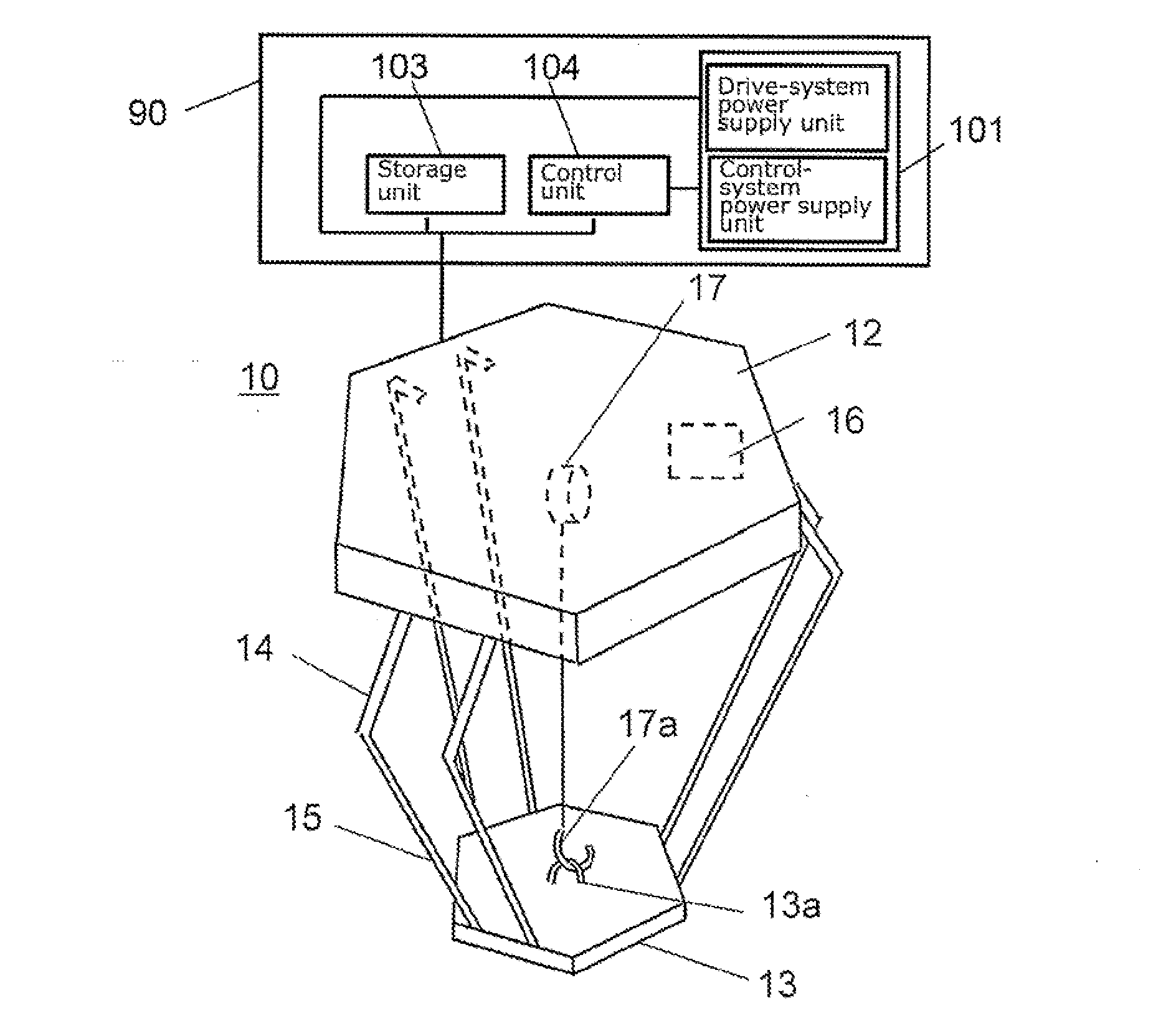
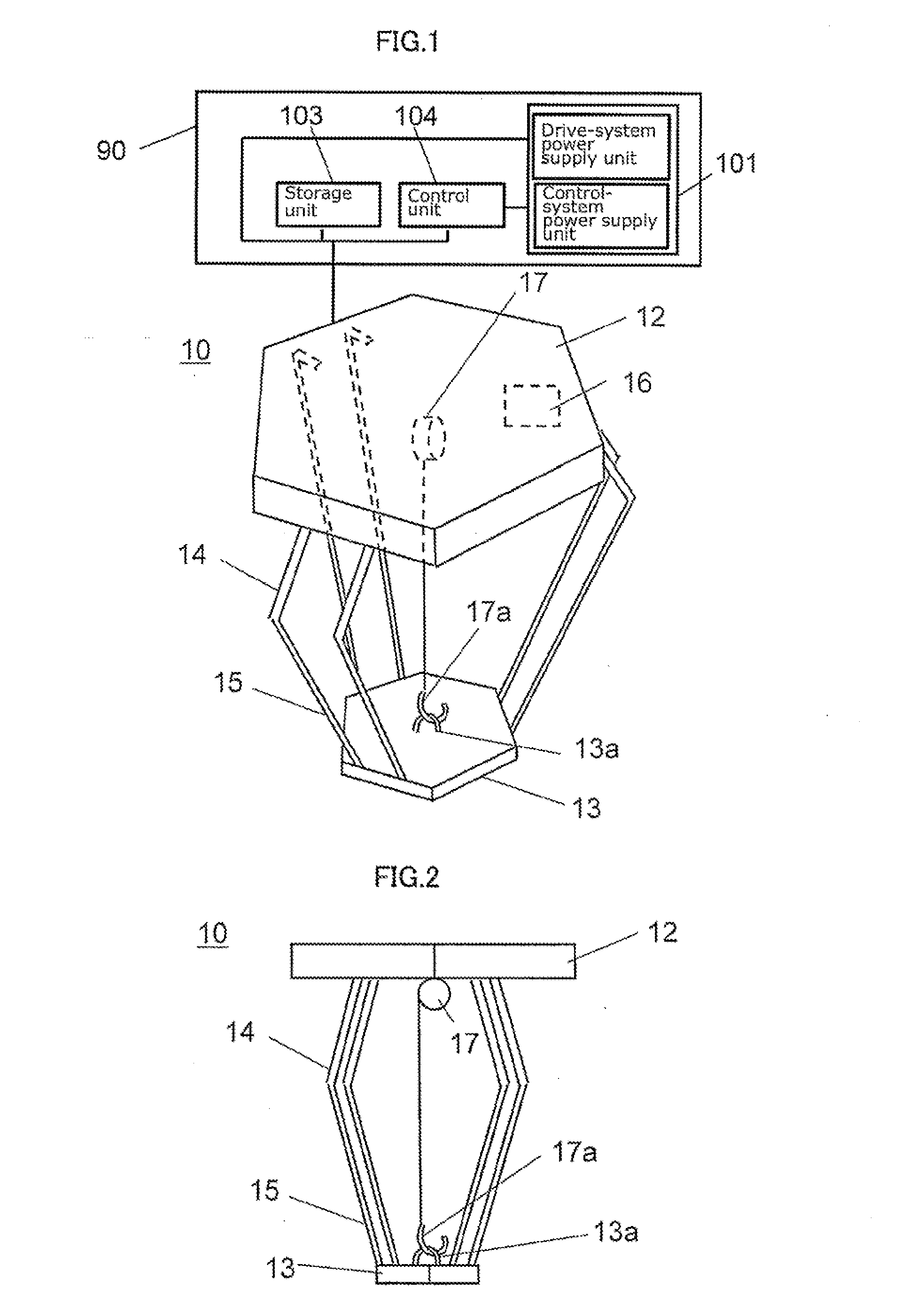
[0025]FIG. 1 is an outline perspective view of a parallel link robot according to a first embodiment of the present invention. FIG. 2 is an outline lateral view of the parallel link robot according to the first embodiment of the present invention. Note that in FIG. 1, a main part of an unseen portion behind the fixing plate that is an example of the base is illustrated with dashed lines. In addition, in FIG. 2, illustrations of the arm and the rod at the back of the drawing surface are omitted.
[0026]In FIGS. 1 and 2, a parallel link robot 10 according to the first embodiment includes: a fixing plate 12 that is an example of the base to which the robot body is fixed; a movable plate 13 that is an example of the movable body to which a working member such as an end effector (for example, a work robot hand) is attached; and three link mechanisms that connect the fixing plate 12 and the movable plate 13. Each link mechanism includes: an arm 14, a rod 15, and a joint. Note that the arm 1...
embodiment 2
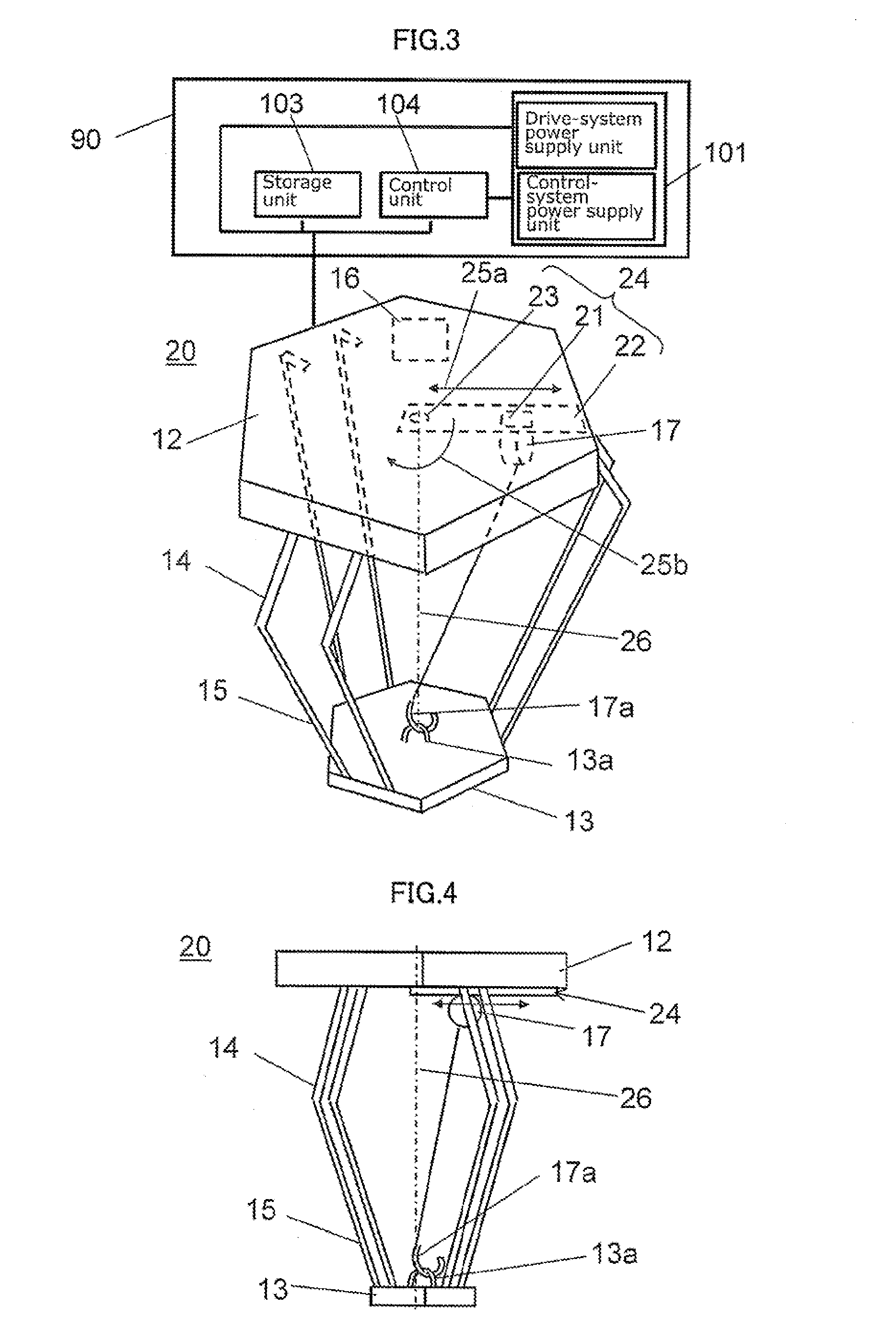
[0043]FIG. 3 is an outline perspective view of a parallel link robot according to a second embodiment of the present invention, and FIG. 4 is an outline lateral view of the parallel link robot according to the second embodiment. Note that in FIG. 3, a main part of an unseen portion behind the fixing plate that is an example of the base is illustrated with dashed lines. In addition, in FIG. 4, illustrations of the arm and the rod at the back of the drawing surface are omitted.
[0044]The parallel link robot 20 according to the second embodiment is different from the first embodiment described earlier in including a slide mechanism which allows moving, within a surface of the fixing plate 12, a support with which the suspension unit 17 is attached to the fixing plate 12. A slide mechanism 24 of the parallel link robot 10 according to the second embodiment includes: a slider 21 attached to the suspension unit 17; and a slide rail 22 along which the slider 21 slides in a (radius) directio...
embodiment 3
[0047]FIG. 5 is an outline perspective view of a parallel link robot according to a third embodiment of the present invention, and FIG. 6 is an outline lateral view of the parallel link robot according to the third embodiment. Note that in FIG. 5, a main part of an unseen portion behind the fixing plate that is an example of the base is illustrated with dashed lines. In addition, in FIG. 6, illustrations of the arm and the rod at the back of the drawing surface are omitted.
[0048]The parallel link robot 30 according to the third embodiment is different from the second embodiment described earlier in that the slide mechanism 24 in the second embodiment includes a slide-tilt mechanism 33 attached to the fixing plate 12 via a tilt mechanism. With this slide-tilt mechanism 33, the distance between the slider 21 and the fixing plate 12 increases as the slider 21 moves toward a peripheral portion (outer edge portion) of the fixing plate 12. Here, that “the distance between the slider 21 an...
PUM
 Abstract
Description
Claims
Application Information