

Physiological signal sensing device, containing device and method for wearing a protective film
- Summary
- Abstract
- Description
- Claims
- Application Information
AI Technical Summary
Benefits of technology
Problems solved by technology
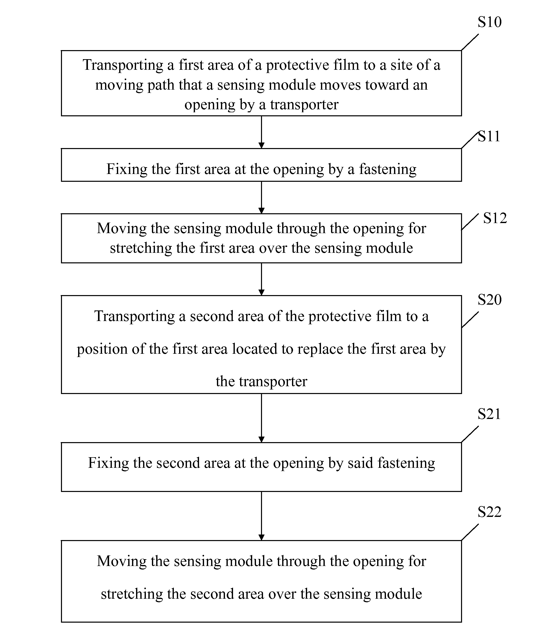
Method used
Image

Examples
first embodiment
[0063]the present invention refers to FIGS. 2A to 2D, and FIGS. 3A to 3D.
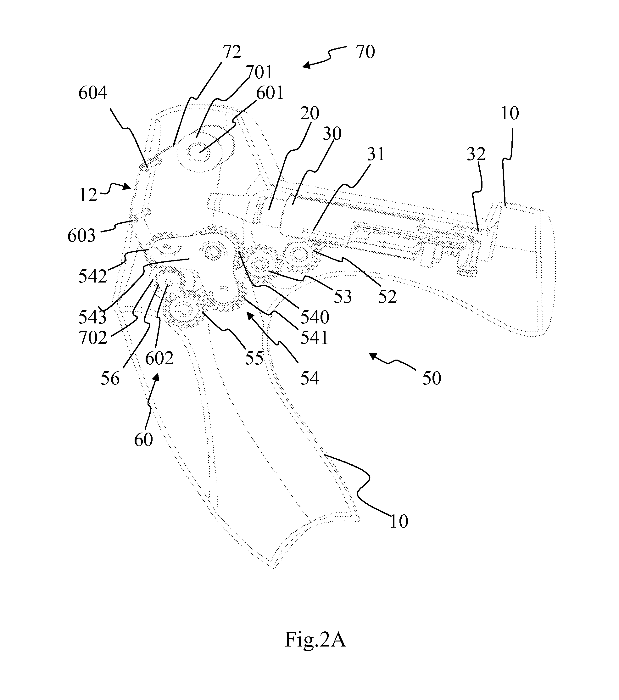
[0064]FIG. 2A is a partial side perspective view of the first embodiment of a physiological signal sensing device in accordance with the present invention. FIG. 2C is a side perspective view showing that a sensing module of the physiological signal in FIG. 2A being moved across a predetermined site.
[0065]Please refer to both FIGS. 2A and 2C, the physiological signal sensing device comprises a housing (10), a sensing module (20), a fastening (30), a controller (40), a driving assembly (50), a transporter (60), a protective-film containing assembly (70) and a protective film (72). FIG. 2A ignores some parts of the fastening (30) and controller (40) at front end surrounding the sensing module (20) in order to mark the location of the sensing module (20) and so does in FIGS. 2B and 2D.
[0066]Please refer to FIG. 2A. The housing (10) includes an opening (12). The sensing module (20) herein is an ear thermometer engag...
second embodiment
[0099]Please refer to both FIGS. 2A and 5, FIG. 5 is a schematic structure view of a physiological signal sensing device in accordance with the present invention. The physiological signal sensing device of the embodiment further comprises a resistant (27) and a following (80) disposed at opposite side relative to the gear (52) and the follower (31) as in FIG. 2A. In another embodiment, the resistant (27) can be disposed at the same side as the gear (52) and the driving assembly (50) is shown in FIG. 2A and connect with the follower (31) referring to FIG. 2A so as to drive it by the follower (31). In this embodiment, when the sensing module (20) is moved toward the opening (12) till the following (80) is engaged with the resistant (27) and then the sensing module (20) keeps being moved, the resistant forms a resisting force against the motion force from the sensing module (20). Whereby, the effect of the motion force from the sensing module (20) can be cushioned. The resistant (27) c...
third embodiment
[0101]Please now refer to FIGS. 6A and 6B, FIG. 6A is a schematic structure view of a physiological signal sensing device in accordance with the present invention showing that the sensing module is moved before a predetermined site. FIG. 6B is a schematic structure view of the physiological signal sensing device referring to FIG. 6A showing that the sensing module is moved over the predetermined site.
[0102]Please refer to FIGS. 2A, 5 and 6A. The physiological signal sensing device of this embodiment works similar to the first embodiment. The difference is that the resistant is an elastic member (28). The elastic member (28) connects with the following (82). In another embodiment, the following (82) can be designed as a part extended out from the sensing module (20). The elastic member (28) has both the function of the fastening (30) referring to FIG. 2A and the function of the resistant (27) referring to FIG. 5. The elastic member (28) is a spring surrounding the sensing module (20)...
PUM
 Abstract
Description
Claims
Application Information