Method and device for manufacturing filtered liquids

Inactive Publication Date: 2012-04-05
KRONES AG
View PDF0 Cites 7 Cited by
  • Summary
  • Abstract
  • Description
  • Claims
  • Application Information

AI Technical Summary

Benefits of technology

[0006]One aspect of the disclosure is to provide a method of the type mentioned in the introduction and a device suitable for carrying out the method with self-monitoring of the maintenance of sterility (filter quality) of the liquid in order to be able to prevent consequential measures arising from the consumption of contaminated liquid.
[0011]In order to achieve a required nominal performance in the production process, it is according to the method also expedient to carry out several parallel, optionally overlapping production cycles in several parallel membrane units. In this case sequential verifications of sterility for the production cycles are obtained and until obtaining the relevant verification of sterility the sum of the production volumes arising so far is temporarily stored. In this way it cannot actually be excluded that, for example, production volumes of perfectly acceptable sterile water are contaminated or at least partly contaminated by a production volume of contaminated sterile water. However, the temporary storage prevents, for example, contaminated sterile water being released as filtered liquid for consumption.
[0012]With a negative result from a conducted membrane functional test at least the content of the temporary store is discarded, because the negative result indicates a membrane fracture or a membrane functional disturbance. The membranes then namely pass the sterile air too quickly or in a too large an amount per unit time, which can be easily determined. Preferably, a cleaning cycle is then carried out, which includes at least the temporary store and the pipework up to the faulty membrane unit. In this way the required interruption of the production process can be relatively short, whereby it is decisive that no contaminated liquid has been released uncontrolled for consumption.
[0016]Expediently, the sterile-air test device is formed for the membrane functional capability such that with the sterile air, which is introduced into the relevant membrane unit at a pressure, a bubble-point test can be carried out which quickly supplies either the verification of sterility so that the production process can continue unchanged or signals a membrane malfunction which can be used to initiate the interruption of the production process.
[0020]Basically, it may be expedient, especially for a continuous operational process, to connect the several membrane units to one common single raw-water pump. The filtration device can thus be operated with a reasonably small energy outlay.

Problems solved by technology

This is an extraordinarily energy-consuming and cost-intensive method.
The membranes of each membrane unit must for example be backwashed at regular intervals, whereby two consecutive backwash cycles and integrity tests temporally limit the production cycle.
A disadvantage of membrane technology is however that so far it has not been possible to economically prove that the membranes remain functionally capable during each functional cycle.
A membrane fracture or a membrane malfunction during a production cycle leads to sterile water of insufficient quality, which may then already have been used during the functions and processes, which implies complex and cost-intensive measures.
This is because a disturbance of this nature is only found too late by a normal membrane integrity test after the production cycle.
The purpose of the reservoir is to make a larger production volume and / or sufficient drinking water immediately available for a backwash cycle, because the membrane unit only has a limited supply performance.
The consumption of contaminated drinking water cannot be prevented in this manner.
A similar problem occurs when apple juice, beer, etc. is filtered or cleared with microfiltration membranes.

Method used


Image

  • Method and device for manufacturing filtered liquids
  • Method and device for manufacturing filtered liquids
  • Method and device for manufacturing filtered liquids

Examples


Embodiment Construction

[0027]The disclosure is explained and described in the following with reference to an ultrafiltration device for the manufacture of sterile water, but the embodiments apply equally to membrane filtration generally and also particularly include microfiltration devices with which, for example, apple juice, beer or similar liquids are filtered or clarified.

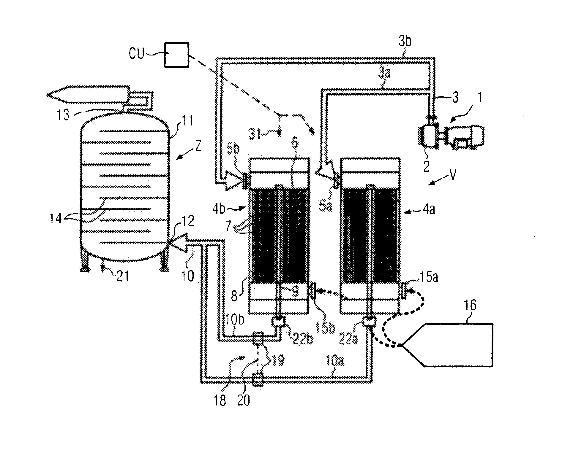
[0028]An ultrafiltration device V in FIG. 1 comprises as the main components a raw-water pumping station 1, at least one membrane unit 4a or 4b, in the illustrated case at least two parallel connected membrane units 4a and 4b and a temporary store Z for sterile water manufactured in the production process.

[0029]In the raw-water pumping station 1, for example for a continuous production process, a single raw-water pump 2 is provided, which pumps raw water via pipework 3 and parallel branch lines 3a, 3b to the inlets 5a, 5b of the membrane units 4a, 4b. In each membrane unit 4a, 4b, for example, an upper potted inlet 6 and a low lying ...


PUM

PropertyMeasurementUnit
Pressureaaaaaaaaaa
Volumeaaaaaaaaaa
Sterileaaaaaaaaaa

Abstract

A method for producing filtered liquid, in particular sterile water, in a filtration device with at least one membrane unit during in each case a production cycle delimited by membrane backwash cycles of each membrane unit, in the production process at least one respective production liquid volume of a production cycle is temporarily stored before release for consumption until a verification of sterility has been obtained for the temporarily stored production liquid volume. In the device a membrane backwash system and a sterile-air test device are assigned to each membrane unit and at least one temporary store having a capacity corresponding at least to the production liquid volume arising during the production cycle is connected downstream.

Description

CROSS-REFERENCE TO RELATED APPLICATION[0001]The present application claims the benefit of priority of German Application No. 102010041826.9, filed Sep. 30, 2010. The entire text of the priority application is incorporated herein by reference in its entirety.FIELD OF THE DISCLOSURE[0002]The disclosure relates to a method and a device for producing a filtered liquid, such as by using a membrane unit.BACKGROUND[0003]For various functions and processes, for example during the manufacture of beverages and in the bottling and packaging industries, sterile water is needed. Sterile water is often produced from raw water by the application of UHT / HTST technology, i.e. by the thermal heating of the raw water to guarantee the mortality of micro-organisms and subsequent cooling to the processing temperature. This is an extraordinarily energy-consuming and cost-intensive method. However, by monitoring the temperature it is relatively easy to ensure the permanent functional capability of the prod...

Claims


Application Information

Patent Timeline
IPC IPC(8): B01D35/00
CPCA23L2/74C02F2303/16B01D61/22B01D65/02B01D65/102B01D2313/50B01D2315/20B01D2321/04C02F1/008C02F1/444C02F2103/02C02F2209/003C02F2209/006C02F2209/03C02F2209/44C02F2303/04B01D61/20
Inventor SCHEU, DIRKLINK, ALBERT
Owner KRONES AG
Why Eureka
Try Eureka