LED bulb structure

Inactive Publication Date: 2012-04-05
ASIA VITAL COMPONENTS SHENZHEN CO LTD
View PDF3 Cites 7 Cited by
  • Summary
  • Abstract
  • Description
  • Claims
  • Application Information

AI Technical Summary

Benefits of technology

[0010]A further object of the present invention is to provide the above LED bulb structure, which has enhanced lighting efficiency.
[0011]To achieve the above and other objects, the LED bulb structure of the present invention includes a base having a first end and a second end opposite to the first end. The first end has a connection section. The second end has an extension section and a surface section. The extension section substantially perpendicularly protrudes from the second end without interfering w

Problems solved by technology

As a result, the lighting efficiency of the LED bulb is poor as a whole.
Also, the projection angle and range

Method used


Image

  • LED bulb structure
  • LED bulb structure
  • LED bulb structure

Examples


Example

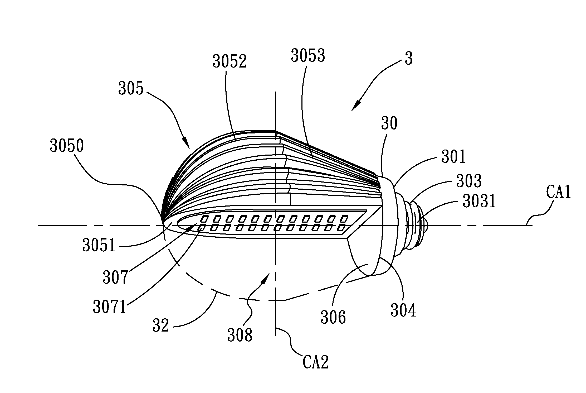
[0021]Please refer to FIGS. 3, 4A and 4B. According to a preferred embodiment, the LED bulb structure 3 of the present invention includes a base 30 and a transparent shell 32. The base 30 has a first end 301 and a second end 304 opposite to the first end 301. The first end 301 has a connection section 303, which is an electrical connector. The connection section 303 has a conductive terminal 3031, which can be locked in a socket 41 on a wall 4 (such as a decorative wall) of a building.

[0022]The second end 304 has an extension section 305 and a surface section 306. The extension section 305 substantially perpendicularly protrudes from the second end 304 (at an angle smaller than or equal to 90 degrees) without interfering with the surface section 306. In other words, the extension section 305 is a protrusion, which has a free end 3050 extending from the second end 304 in a direction away from the base 30.

[0023]The extension section 305 further has a mount face 3051 and a heat dissipa...


PUM


Abstract

An LED bulb structure includes a base having a first end and a second end. The first end has a connection section. The second end has a surface section and an extension section substantially perpendicularly protruding from the second end without interfering with the surface section. The extension section has a mount face on which an LED module is disposed and a heat dissipation section disposed on an outer surface of the extension section. a transparent space being defined between the mount face and the surface section. When the LED bulb structure is horizontally locked in a socket on a wall of a building, the projection angle and range of the LED module are modified to enhance lighting efficiency of the LED module.

Description

FIELD OF THE INVENTION[0001]The present invention relates to an LED bulb structure, and more particularly to an LED bulb structure in which the projection angle of the LED module is modified to enhance lighting efficiency of the LED module.BACKGROUND OF THE INVENTION[0002]In comparison with a conventional light bulb, an LED bulb has the advantages of power saving and high durability. Therefore, the LED bulb has higher and higher market share nowadays.[0003]Please refer to FIGS. 1, 2A and 2B. A conventional LED bulb structure 1 includes a heat dissipation base 10 and a transparent shell 12 correspondingly connected with the heat dissipation base 10 to cover the same. The heat dissipation base 10 has a first end proximal to the transparent shell and a second end distal from the transparent shell. Multiple LED chips 13 are arranged on an end face of the first end of the heat dissipation base 10. The heat dissipation base 10 has a heat dissipation section 101 and an electrical connectio...

Claims


Application Information

Patent Timeline
IPC IPC(8): H01J61/52
CPCF21K9/13F21S8/033F21Y2101/02F21V29/777F21V29/75F21V29/767F21Y2105/001F21K9/23F21Y2105/10F21Y2115/10
Inventor HUANG, CHIU-MAO
Owner ASIA VITAL COMPONENTS SHENZHEN CO LTD
Why Eureka
Try Eureka