Image processing system

Active Publication Date: 2012-04-05
EVIDENT CORP
View PDF4 Cites 16 Cited by
  • Summary
  • Abstract
  • Description
  • Claims
  • Application Information

AI Technical Summary

Problems solved by technology

Also, small-scale medical facilities lacking staining equipment for specimens will often commission specimen staining to medical facilities that do have staining equipment.

Method used


Image

  • Image processing system
  • Image processing system
  • Image processing system

Examples


first embodiment

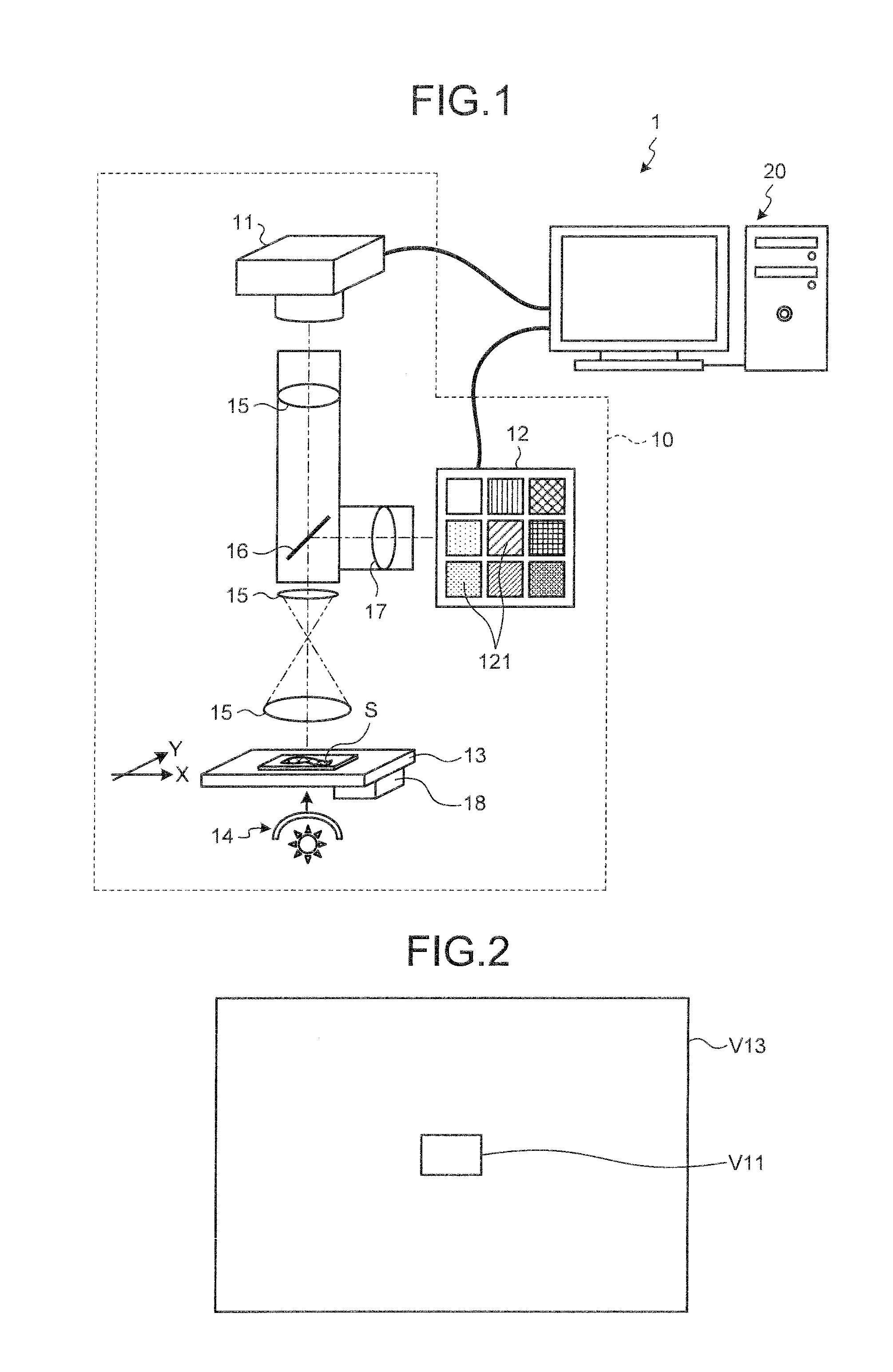
[0078]FIG. 1 is a schematic diagram illustrating an example of the overall configuration of an image processing system 1 in a first embodiment. As illustrated in FIG. 1, in the image processing system 1, a microscope imaging system 10 and a computer 20 such as a personal computer configured to be connected so as to be able to send and receive data.

[0079]The microscope imaging system 10 performs RGB image capturing on a partial region or the entire region of the target specimen (hereinafter called the “RGB imaging area”) to acquire RGB signal values, and also performs multiband image capturing on a prescribed view within the RGB imaging area (hereinafter called the “multiband signal acquisition view”) to acquire multiband signal values. In addition to an RGB signal acquisition unit 11 serving as a multiband image acquisition unit for acquiring RGB signal values and a multiband signal acquisition unit 12 for acquiring multiband signal values, the microscope imaging system 10 further i...

first modification

[0141]In the first embodiment, plural spectral properties are generated for the H dye and for the E dye using the spectral property change model, and one is selected from those generated in order to determine the spectral property of the H dye and the E dye used to stain the target specimen. In particular, the standard dye spectral properties of the H dye and the E dye are changed by giving a plurality of values of each variable (α, γ, λ1, λ2) for the conversion Equations (27), (28) of the spectral properties k(λ) of the dyes in order to generate plural new spectral properties for the H dye and the E dye, where the one with the highest evaluation is determined as the spectral property of the H dye and the E dye. In such a case, processing time increases proportionately to the number of combinations of values for each variable (α, γ, λ1, λ2). Therein, a known genetic algorithm (GA) may be used to generate the spectral properties of the H dye and the E dye, thus determining the spectr...

second modification

[0155]In the first embodiment, a description is provided for when a single target specimen image acquired by performing an RGB image capturing on the RGB imaging area of the target specimen is processed, but a similar application is possible for when processing on plural target specimen images obtained by performing the RGB image capturing on different points of the target specimen while actuating the stage 13 of the microscope imaging system 10 on the XY plane.

[0156]FIG. 13 is a diagram illustrating the RGB imaging areas V31 of the plural target specimen images to be subjected to the RGB image capturing, and the multiband signal acquisition view V33 within each RGB imaging area V31. In the second modification, by taking RGB photographs at each position (capturing positions) when the stage 13 is being actuated on the XY plane per each RGB imaging area V31 and acquiring plural target specimen images (15 images in FIG. 13) obtained by performing the RGB image capturing on adjacent RGB...


PUM


Abstract

Provided is an image processing system including a multiband signal acquisition unit and a dye spectral property determining unit. The multiband signal acquisition unit acquires a multiband signal value of a subject specimen that has been stained with H&E dyes. The dye spectral property determining unit generates new spectral properties of the H dye and the E dye by varying standard spectral properties previously set to each of the H dye and the E dye according to a spectral property change model, and determines the spectral properties of the H dye and the E dye based on the generated new spectral properties and multiband signal values.

Description

CROSS REFERENCE TO RELATED APPLICATIONS[0001]This application is based upon and claims the benefit of priority from Japanese Patent Application No. 2010-222803, filed on Sep. 30, 2010, the entire contents of which are incorporated herein by reference.BACKGROUND OF THE INVENTION[0002]1. Field of the Invention[0003]The present invention relates to an image processing system for acquiring the spectral properties of a dye used to stain a specimen.[0004]2. Description of the Related Art[0005]One of the physical quantities expressing a physical property specific to a subject is transmittance. Transmittance is a physical quantity representing the ratio of transmitted light to incident light at each wavelength, and is information that is inherent to an object, having a value that is not affected by outside influences, unlike color information like the RGB value, which varies depending on changes in illumination light. Thus, transmittance is used in various fields of application as informati...

Claims


Application Information

Patent Timeline
Patent Type & Authority Applications(United States)
IPC IPC(8): G06K9/00
CPCG06T7/408G06T2207/30024G06T2207/10056G06T7/90
Inventor TANI, SHINSUKE
Owner EVIDENT CORP
Why Eureka
Try Eureka