Charging roller, image forming apparatus, and recycling method

Active Publication Date: 2012-04-05
SHARP KK
View PDF3 Cites 2 Cited by
  • Summary
  • Abstract
  • Description
  • Claims
  • Application Information

AI Technical Summary

Benefits of technology

[0015]According to the charging roller of the present invention, it is possible to replace the gap securing member by a new one, without reducing the effective width of the charge emission surface of the charge emission member. This enables a larger number of replacements of the gap securing member, thereby enabling the charging roller to be used for a long time.

Problems solved by technology

However, such a charging roller has caused a problem that a partial deterioration occurs at a boundary, in the charge emission member, between an area where the gap retaining member is attached and an area where no retaining member is attached.

Method used


Image

  • Charging roller, image forming apparatus, and recycling method
  • Charging roller, image forming apparatus, and recycling method
  • Charging roller, image forming apparatus, and recycling method

Examples


Embodiment Construction

[0022]An embodiment of the present invention will be described below. The following description will mainly discuss a case where the present invention is applied to a monochrome image forming apparatus in the present embodiment. Note that the present invention is not limited to this, and can therefore be applied to a color image forming apparatus.

[0023][Entire Configuration of the Multifunction Printer 10]

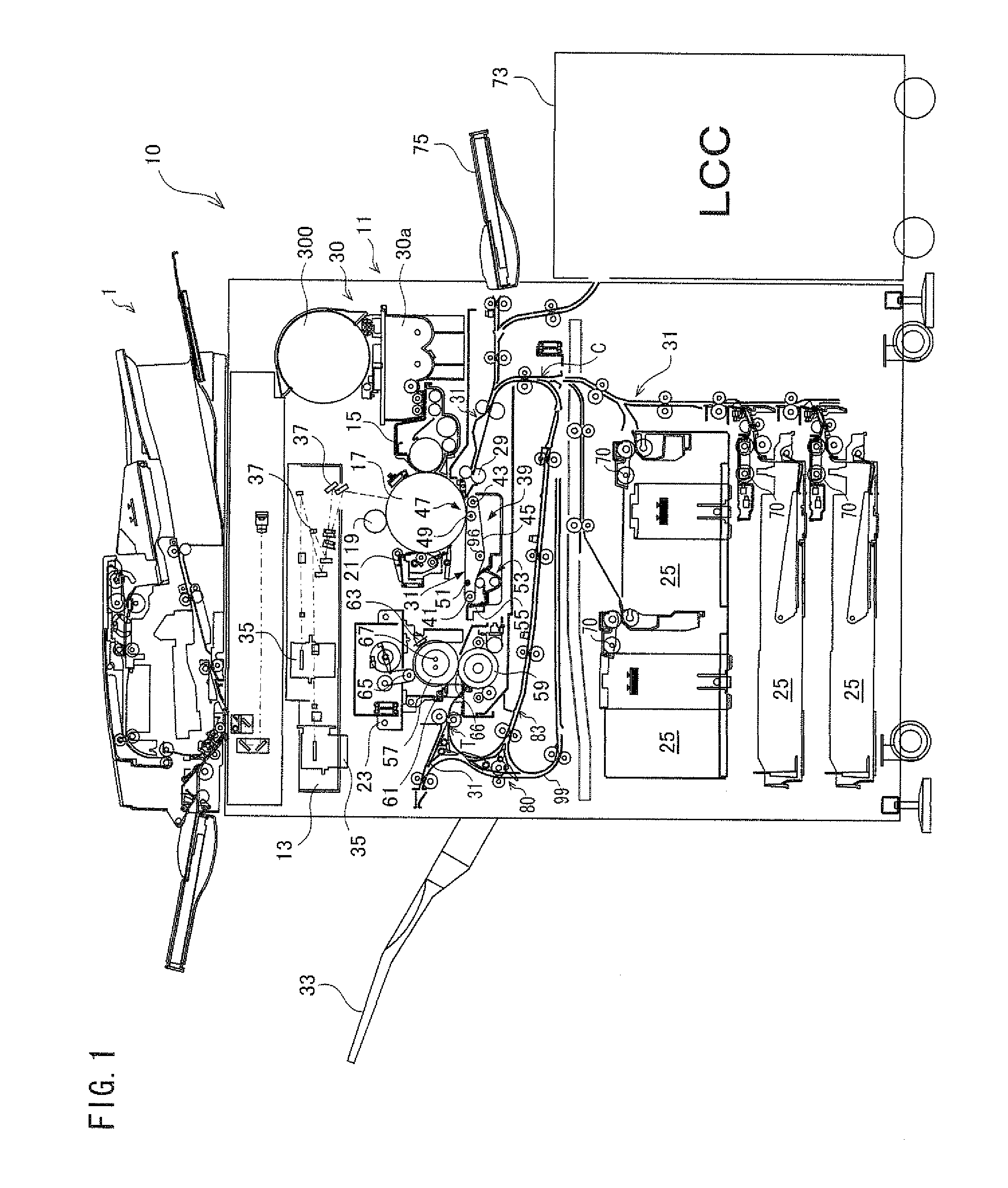
[0024]FIG. 1 is a cross-sectional view schematically illustrating an entire configuration of a multifunction printer 10 including an image forming apparatus 11 in accordance with the present embodiment. As illustrated in FIG. 1, the multifunction printer 10 includes a scanner 1 and the image forming apparatus 11.

[0025]The scanner 1 scans a document so as to obtain an image data of the document. A conventionally known scanner can be used as the scanner 1.

[0026]The image forming apparatus 11 forms, on a sheet of paper, an image in accordance with (i) image data obtained by scanning a...


PUM

PropertyMeasurementUnit
Electrical conductoraaaaaaaaaa
Torqueaaaaaaaaaa

Abstract

A charging roller has a conductive shaft, a charge emission member provided to the shaft, and a gap securing member provided to the shaft. The gap securing member (i) protrudes toward the photoreceptor drum so as to be closer to the photoreceptor drum than the charge emission member is to the photoreceptor drum and (ii) is in contact with the photoreceptor drum so as to secure a gap between the charge emission member and the photoreceptor drum. A conductive part of the gap securing member and the shaft are bonded to each other by electrically releasing adhesive, so that the gap securing member is provided to the shaft.

Description

[0001]This Nonprovisional application claims priority under 35 U.S.C. §119(a) on Patent Application No. 2010-224267 filed in Japan on Oct. 1, 2010, the entire contents of which are hereby incorporated by reference.TECHNICAL FIELD[0002]The present invention relates to a charging roller to be attached to an electrophotographic image forming apparatus.BACKGROUND ART[0003]A charging roller, attached to electrophotographic image forming apparatuses so as to charge photoreceptor drums, has been conventionally known. The charging roller has a shaft and a charge emission member (roller main body) attached to the shaft, and charge a photoreceptor drum by means of an electric charge emitted from the charge emission member.[0004]A charging roller, as disclosed in Patent Literature 1, has been conventionally known in which a gap retaining member, attached to a part of a charge emission member, is caused to be in contact with a photoreceptor drum. This allows the photoreceptor drum and the charg...

Claims


Application Information

Patent Timeline
IPC IPC(8): G03G15/02B32B38/10
CPCG03G15/025
Inventor ISHIGURO, YASUYUKINAGAHAMA, HITOSHI
Owner SHARP KK
Why Eureka
Try Eureka