External resonator electrode-less plasma lamp and method of exciting with radio-frequency energy

a plasma lamp and external resonator technology, applied in the field of plasma lamps, can solve the problems of limited lifetime, difficult to couple energy into smaller bulbs, and deterioration of electrodes, and achieve the effect of reducing lamp costs, extending lamp application range, and facilitating the effect of impedance matching to the bulb very efficiently

Inactive Publication Date: 2012-04-12
TOPANGA USA
View PDF7 Cites 6 Cited by
  • Summary
  • Abstract
  • Description
  • Claims
  • Application Information

AI Technical Summary

Benefits of technology

[0009]This invention provides distinct advantages over electrode-less plasma lamps in the background art. Firstly, using an external resonator or cavity structure enables lamp operation at frequencies well below 1 GHz, lowering lamp cost and extending the range of lamp applications. Moreover, in the present invention, it is possible to impedance match to the bulb very efficiently and relatively independently of the value of the coupling capacitor by using a high Q resonator in addition to the coupling capacitor, thus allowing efficient coupling of RF energy into any size bulb (gas-fill vessel). Furthermore during lamp start-up and warm-up the resonant frequency of the resonator does not shift significantly, eliminating the need for additional circuitry. Whereas the ability to collect light is a serious drawback of the approaches previously discussed in the art, the physical separation of the lamp from the dielectric waveguide body or the resonant cavity provided by this invention allows increased light harvesting. In addition, the lamp has significantly better etendue, which is a critical parameter for light sources used for projection systems such as lamps for rear projection televisions (RPTVs) and front projectors. Finally, by removing the fundamental compromise between dimensions of the dielectric waveguide body and operating frequency, this invention makes it possible to substantially reduce lamp size to again extend the range of applications. Moreover, in addition to these three substantial advantages, these lamps still form bright, spectrally-stable sources that exhibit energy efficiency and long lifetimes. Rather than incorporating the gas-fill vessel as a subset of the dielectric waveguiding body, the bulb is capacitively driven by an external resonator that delivers the required field to the gas-fill vessel to ignite the plasma and then sustains the plasma.
[0016]In yet another aspect, the plasma electrode-less lamp further comprises a reflector. The reflector is coupled to the conductive veneer of the RF electromagnetic resonator. The reflector has a shape such that light emitted from the gas-fill vessel is substantially collected and substantially directed, focused, or collimated. The grounding strap is a wire mesh that couples to the reflector with the first conductive veneer of the gas-fill vessel without substantially obstructing light emanating from the reflector. The mesh further provides electromagnetic interference shielding for the RF plasma electrode-less lamp.
[0018]In yet another aspect, the plasma electrode-less lamp further comprises a center conductor coupled to the output probe with the second conductive veneer of the gas-fill vessel; an outer conductor coupled to the grounding strap with the conductive veneer of the RF electromagnetic resonator; and a length such that the RF electromagnetic resonator is substantially impedance matched to the gas-fill vessel. Thus light collection efficiency is substantially improved by raising the gas-fill vessel substantially away from the RF electromagnetic resonator.
[0024]In yet another aspect, the plasma electrode-less lamp further comprises a reflector. The reflector is coupled to the conductive veneer of the RF electromagnetic resonator. The reflector has a shape such that light emitted from the gas-fill vessel is substantially collected and substantially directed, focused, or collimated, and wherein the grounding strap is a wire mesh that couples to the reflector with the first conductive veneer of the gas-fill vessel without substantially obstructing light emanating from the reflector. The mesh further provides electromagnetic interference shielding of the gas-fill vessel.
[0026]In yet another aspect, the plasma electrode-less lamp further comprises a coaxial transmission line. The coaxial transmission line comprises a center conductor coupled to the output probe with the second conductive veneer of the gas-fill vessel; an outer conductor coupled to the grounding strap with the conductive veneer of the RF electromagnetic resonator; and a length such that the RF electromagnetic resonator is substantially impedance matched to the gas-fill vessel. Thus light collection efficiency is improved by raising the gas-fill vessel substantially away from the RF electromagnetic resonator.
[0031]In yet another aspect, the plasma electrode-less lamp comprises a gas-fill vessel. The gas-fill vessel comprises a closed, transparent body comprising a first end, a second end, an outer surface, and an inner surface, the inner surface forming a cavity. The gas-fill vessel further comprises a first refractory veneer substantially covering a first portion of the body of the gas-fill vessel; a second refractory veneer substantially covering a second portion of the body of the gas-fill vessel; a first conductive veneer substantially covering the first refractory veneer; and a second conductive veneer substantially covering the second refractory veneer. The plasma electrode-less lamp further comprises a gas-fill contained within the gas-fill vessel, the gas-fill comprising a fill material and an inert gas. The plasma electrode-less lamp further comprises an RF electromagnetic radiation source comprising an RF electromagnetic oscillator and an RF amplifier comprising an RF amplifier input coupled to the RF electromagnetic oscillator and an RF amplifier output. The plasma electrode-less lamp further comprises an RF electromagnetic resonator comprising a toroidal body comprising a dielectric material with a surface and a central hole; a conductive veneer substantially covering the surface of the toroidal body and inside the central hole; an output opening in the conductive veneer; and an input opening in the conductive veneer. The plasma electrode-less lamp further comprises an output probe coupled to the first conductive veneer of the gas-fill vessel. The output probe being at least one of e-field probe, h-field probe, or patch antenna. The output probe intersects the output end substantially within the output opening. The size, shape, and position of the output probe create substantial impedance matching between the RF electromagnetic resonator and the gas-fill vessel. The plasma electrode-less lamp further comprises an input probe coupled to the RF amplifier output of the RF electromagnetic radiation source. The input probe being at least one of e-field probe, h-field probe, or patch antenna. The input probe intersects the input end substantially within the input opening. The size, shape, and position of the input probe create substantial impedance matching between the RF electromagnetic resonator and the RF electromagnetic radiation source. Finally, the plasma electrode-less lamp further comprises a grounding strap coupled to the first conductive veneer of the gas-fill vessel with the conductive veneer of the RF electromagnetic resonator. Thus RF electromagnetic radiation is coupled to the gas via the RF electromagnetic resonator, which forms a plasma that heats the fill material and thus causes the fill material to emit light.

Problems solved by technology

This arrangement, however, suffers from electrode deterioration due to sputtering of the metal electrodes, and therefore exhibits a limited lifetime.
In particular, it is more difficult to couple energy into smaller bulbs because of the smaller value of the coupling capacitance.
The waveguide body surrounding the bulb brings with it a host of difficulties including wasted light, poor etendue, lamp size related to resonance or excitation frequency, shift in resonant frequency during lamp start-up / warm-up requiring additional circuitry and complexity, manufacturing obstacles, and related costs.

Method used


Image

  • External resonator electrode-less plasma lamp and method of exciting with radio-frequency energy
  • External resonator electrode-less plasma lamp and method of exciting with radio-frequency energy
  • External resonator electrode-less plasma lamp and method of exciting with radio-frequency energy

Examples


Embodiment Construction

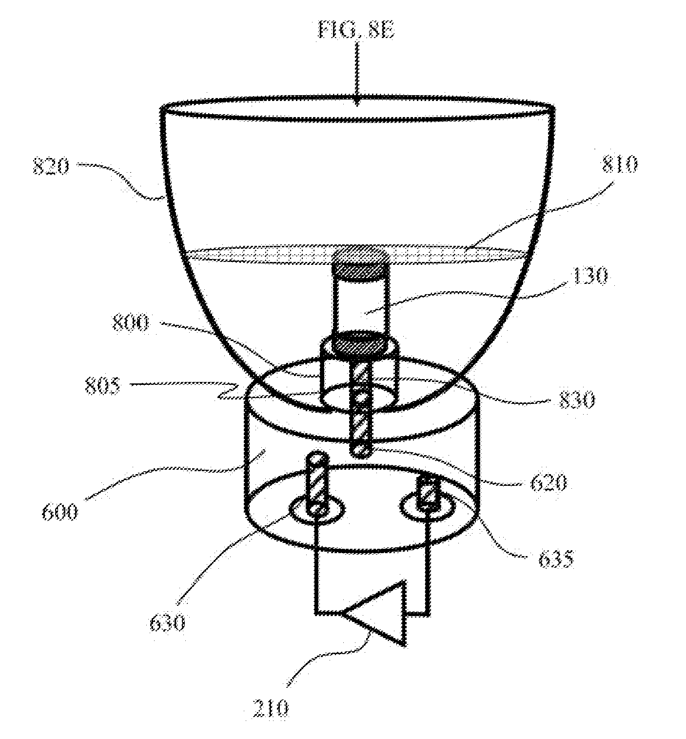
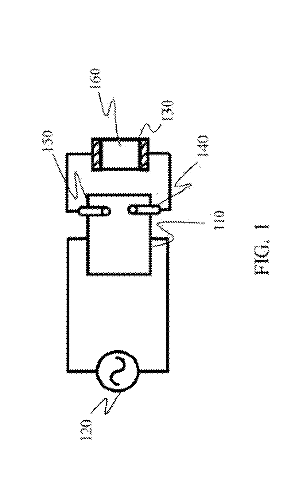
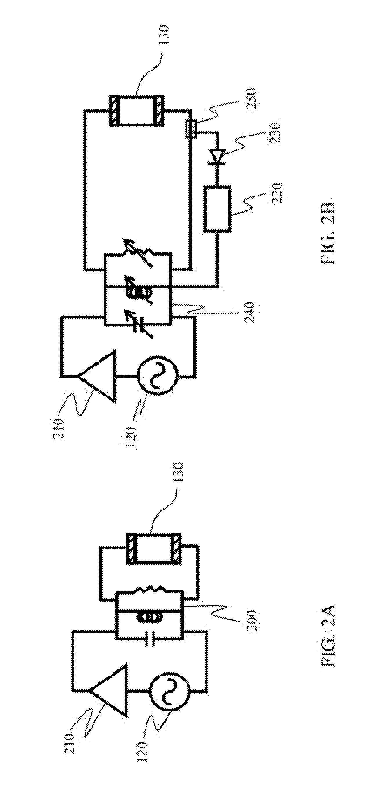
[0099]The present invention relates to a plasma lamp and, more particularly, to a plasma lamp without internal electrodes and having a gas-fill vessel that is not contiguous with (detached from) any RF / microwave cavities or resonators. The following description is presented to enable one of ordinary skill in the art to make and use the invention and to incorporate it in the context of particular applications. Various modifications, as well as a variety of uses in different applications will be readily apparent to those skilled in the art, and the general principles defined herein may be applied to a wide range of embodiments. Thus, the present invention is not intended to be limited to the embodiments presented, but is to be accorded the widest scope consistent with the principles and novel features disclosed herein.

[0100]In the following detailed description, numerous specific details are set forth in order to provide a more thorough understanding of the present invention. However,...


PUM


Abstract

Described is an electrode-less plasma lamp comprising a gas-fill vessel, a gas-fill contained within the gas-fill vessel, an RF electromagnetic radiation source, an RF electromagnetic resonator, an output probe that couples RF energy from the RF electromagnetic resonator to the gas-fill vessel, an input probe that couples RF energy from the RF electromagnetic radiation source to the resonator, and a grounding strap that holds a metal veneer surrounding the resonator and a portion of the gas-fill vessel at RF ground. Also described are many variations of the electrode-less plasma lamp; non-limiting examples of which include embodiments that employ other probes in a Dielectric Resonant Oscillator to drive the lamp, and many methods of improving light-harvesting, including raising the gas-fill vessel away from the resonator via a coaxial type transmission line, and collecting light with an optical reflector.

Description

PRIORITY CLAIM[0001]The present invention is a Continuation of U.S. Non-Provisional application Ser. No. 11 / 981,884 filed Oct. 31, 2007, entitled, “External Resonator Electrode-less Plasma Lamp and Method of Exciting with Radio-Frequency Energy,” which is a Continuation-in-Part patent application, claiming the benefit of priority of U.S. Non-Provisional application Ser. No. 11 / 543,736, filed on Oct. 4, 2006, entitled “External Resonator / Cavity Electrode-less Plasma Lamp and Method of Exciting with Radio-Frequency Energy,” now issued as U.S. Pat. No. 7,291,985, which further claims the benefit of priority of U.S. Provisional Application No. 60 / 723,144, filed on Oct. 4, 2005, entitled, “External Resonator / Cavity Electrode-less Plasma Lamp and Method of Exciting with Radio-Frequency Energy.”BACKGROUND[0002](1) Field[0003]The field of the present invention relates to devices and methods for generating light, more particularly to the field of plasma lamps, and still more particularly to ...

Claims


Application Information

Patent Timeline
Patent Type & Authority Applications(United States)
IPC IPC(8): H01J65/04H05B41/16
CPCH01J65/042Y02B20/22H05B41/2806H01J65/046Y02B20/00
Inventor ESPIAU, FREDERICK MATTHEWMATLOUBIAN, MEHRAN
Owner TOPANGA USA
Why Eureka
Try Eureka