Method of locating touch position

Inactive Publication Date: 2012-04-12
AU OPTRONICS CORP
View PDF28 Cites 22 Cited by
  • Summary
  • Abstract
  • Description
  • Claims
  • Application Information

AI Technical Summary

Benefits of technology

[0009]As described above, in the touch position locating method provided by the invention, a position touched by a user on an optical touch panel can be precisely located after an AND operation is performed on the first binary codes and the second binary codes respectively conve

Problems solved by technology

However, such an optical touch panel may produce a m

Method used


Image

  • Method of locating touch position
  • Method of locating touch position
  • Method of locating touch position

Examples


Embodiment Construction

[0021]Reference will now be made in detail to the present preferred embodiments of the invention, examples of which are illustrated in the accompanying drawings. Wherever possible, the same reference numbers are used in the drawings and the description to refer to the same or like parts.

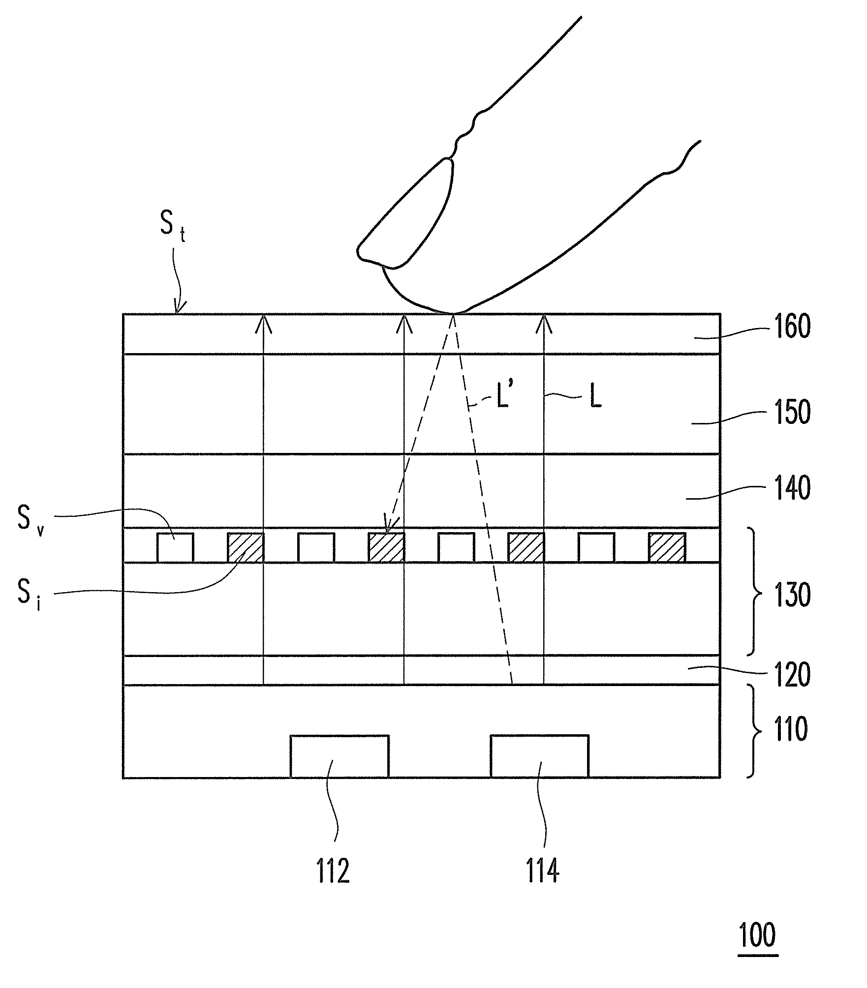
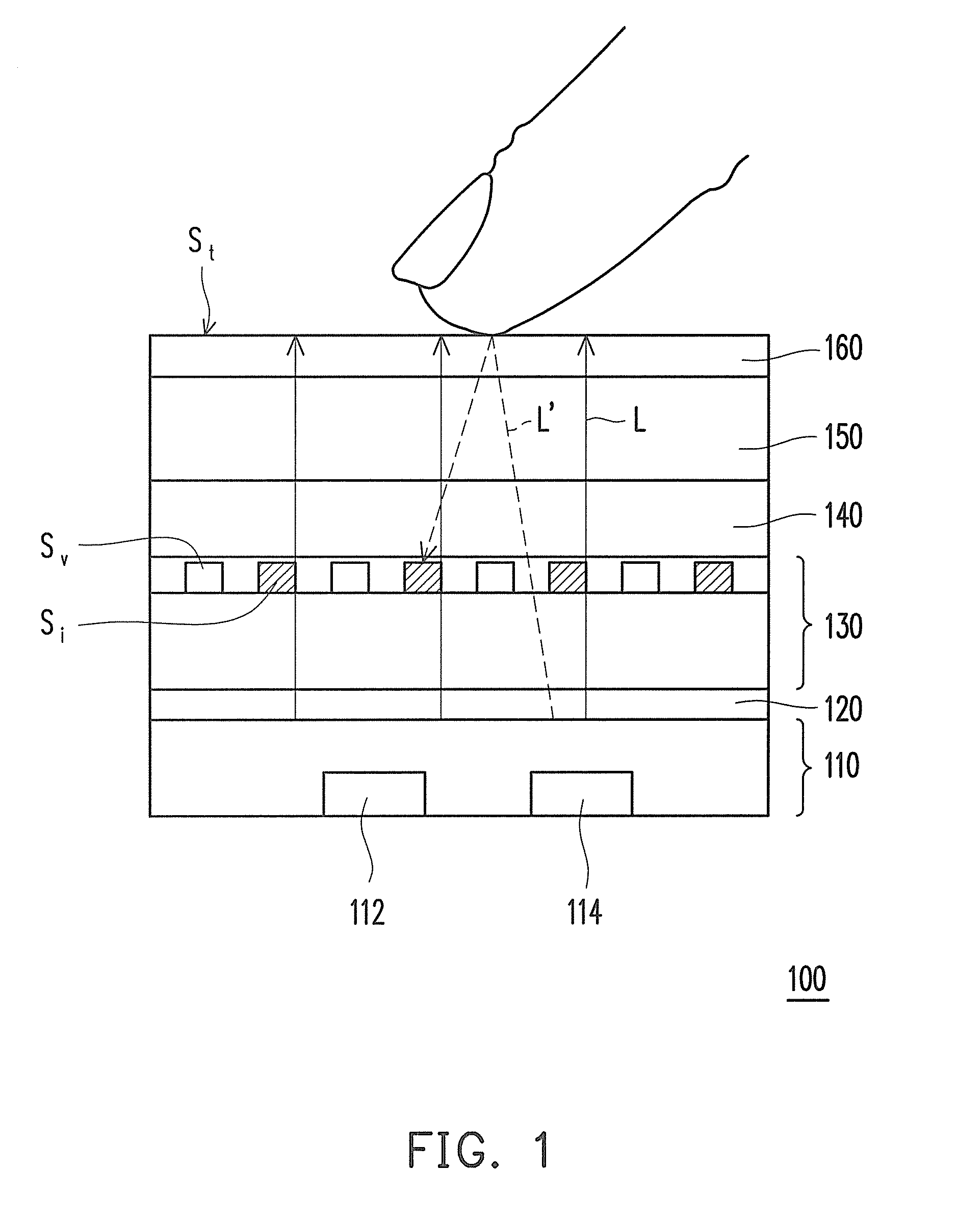
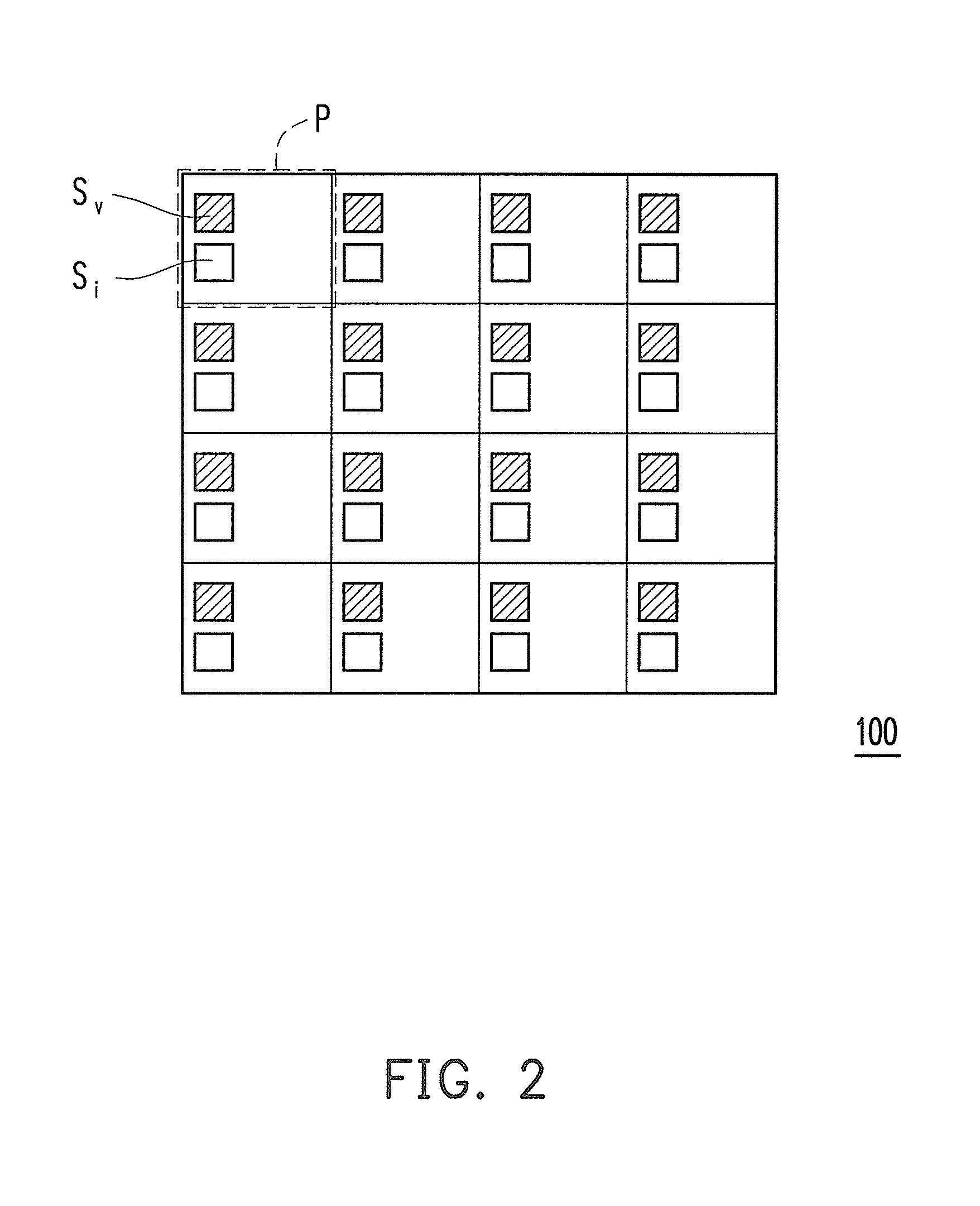
[0022]FIG. 1 is a diagram illustrating an optical touch panel to which a touch position locating method is adaptable according to an embodiment of the invention. Referring to FIG. 1, in the present embodiment, the optical touch panel 100 includes a plurality of visible light sensors Sv and a plurality of corresponding invisible light sensors Si that are arranged as an array. For example, the optical touch panel 100 includes 4×4 visible light sensors Sv arranged as an array and 4×4 invisible light sensors Si arranged as an array, and the visible light sensors Sv are respectively corresponding to the invisible light sensors Si. Preferably, each visible light sensor Sv and the corresponding invisible li...


PUM


Abstract

A method for locating a touch position is provided. The method is adaptable to an optical touch panel, wherein the optical touch panel has a plurality of visible light sensors and a plurality of corresponding invisible light sensors that are arranged as an array. In the present method, sensing signals of the visible light sensors and the invisible light sensors are read. The sensing signal of each visible light sensor is converted into a first binary code according to a first setting parameter, and the sensing signal of each invisible light sensor is converted into a second binary code according to a second setting parameter and a third setting parameter. An AND operation is performed on all the first binary codes and all the second binary codes to obtain a plurality of logic operation values, so as to locate a position touched by a user on the optical touch panel.

Description

CROSS-REFERENCE TO RELATED APPLICATION[0001]This application claims the priority benefit of Taiwan application serial no. 99134411, filed on Oct. 8, 2010. The entirety of the above-mentioned patent application is hereby incorporated by reference herein and made a part of this specification.BACKGROUND OF THE INVENTION[0002]1. Field of the Invention[0003]The invention generally relates to a touch technology, and more particularly, to a method of locating a touch position on an optical touch panel.[0004]2. Description of Related Art[0005]Along with the rapid advancement of information and wireless communication technologies and the widespread of information appliances, the input devices of many information products have been changed from conventional keyboards and mice to touch panels in order to achieve a more personalized operation experience. Presently, touch panels are generally categorized into resistive touch panels, capacitive touch panels, surface acoustic wave (SAW) touch pane...

Claims


Application Information

Patent Timeline
IPC IPC(8): G06F3/042
CPCG06F3/0421G06F3/0416
Inventor TSENG, HUNG-WEIPAI, CHENG-CHIUTZENG, SHU-WENCHO, AN-THUNG
Owner AU OPTRONICS CORP
Why Eureka
Try Eureka