
Surgical method for repairing a fractured shoulder joint

a shoulder joint and surgical technology, applied in the field of surgical methods for repairing a fractured shoulder joint, can solve the problems of affecting the operation of the restored joint, not completely satisfactory, and not optimally obtained ligamentary and muscular tension

Active Publication Date: 2012-04-12
FX SOLUTIONS
View PDF4 Cites 40 Cited by
  • Summary
  • Abstract
  • Description
  • Claims
  • Application Information

AI Technical Summary

Benefits of technology

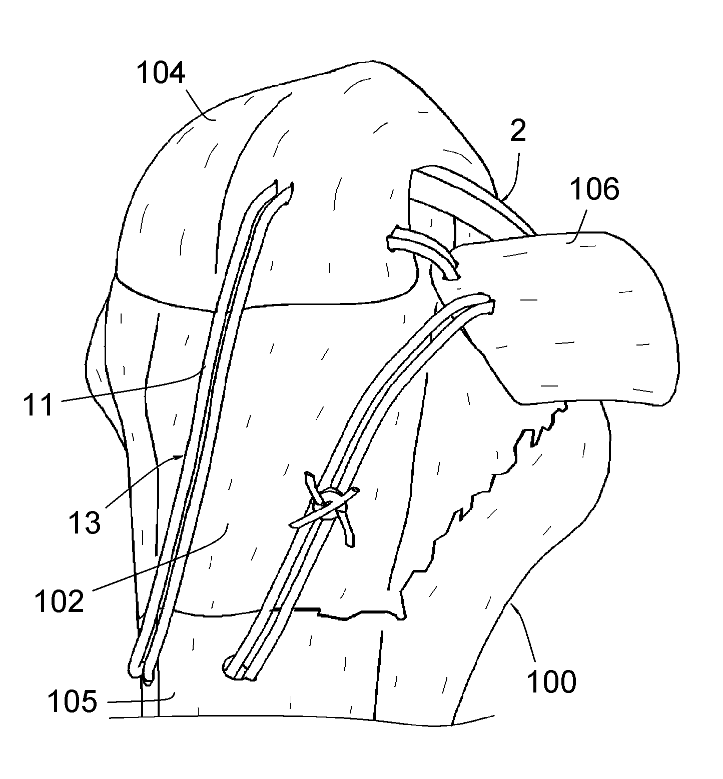
[0018]while the joint is in neutral rotation, or external rotation, applying the tuberosities on the humeral rod without blocking them; then pulling on the threads of said traction subassemblies so as to tighten the aforementioned choker knots and obtain a balance of the muscle tensions produced by the subscapularis muscle and the infraspinatus / supraspinous muscle, then knotting said threads together while preserving that balance; a traction of the tuberosities toward each other is thus achieved;
[0020]engaging the thread of the guying subassembly through the tendon of the subscapularis muscle from the outside in, and through the tendon of the supraspinous muscle, from the inside out, then stretching that thread and knotting it with itself; strengthened guying of the reconstituted bone 100 is thus achieved.
[0021]The invention consequently provides a surgical method for repairing a fractured shoulder joint, consisting of combining (i) a humeral rod comprising an anteroposterior hole formed in its metaphyseal portion, and (ii) five subassemblies with needle and thread forming loops; this assembly making it possible to perfectly:
[0025]As a result, the assembly according to the invention enables precise repositioning of the tuberosities and complete immobilization thereof relative to the rest of the bone, favorable to the consolidation of the entire bone.

Problems solved by technology

Failing this, the obtained ligamentary and muscular tensions are not optimal, which noticeably affects the operation of the restored joint.
This technique is not completely satisfactory, as it can lead to relatively imprecise repositioning of the tuberosities and insufficient immobilization thereof relative to the rest of the bone, affecting the consolidation of the latter.

Method used


Image

  • Surgical method for repairing a fractured shoulder joint
  • Surgical method for repairing a fractured shoulder joint
  • Surgical method for repairing a fractured shoulder joint

Examples


Embodiment Construction

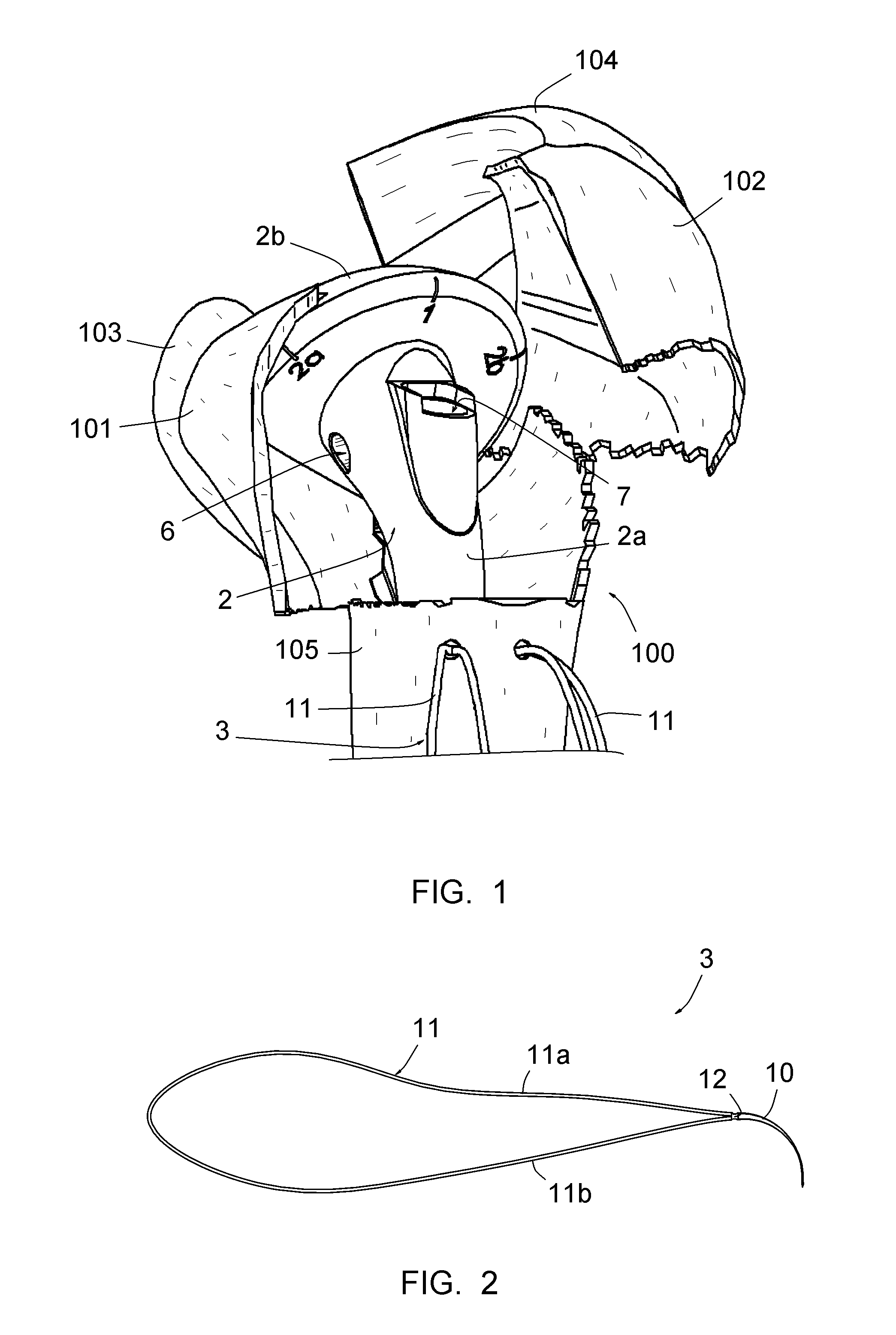
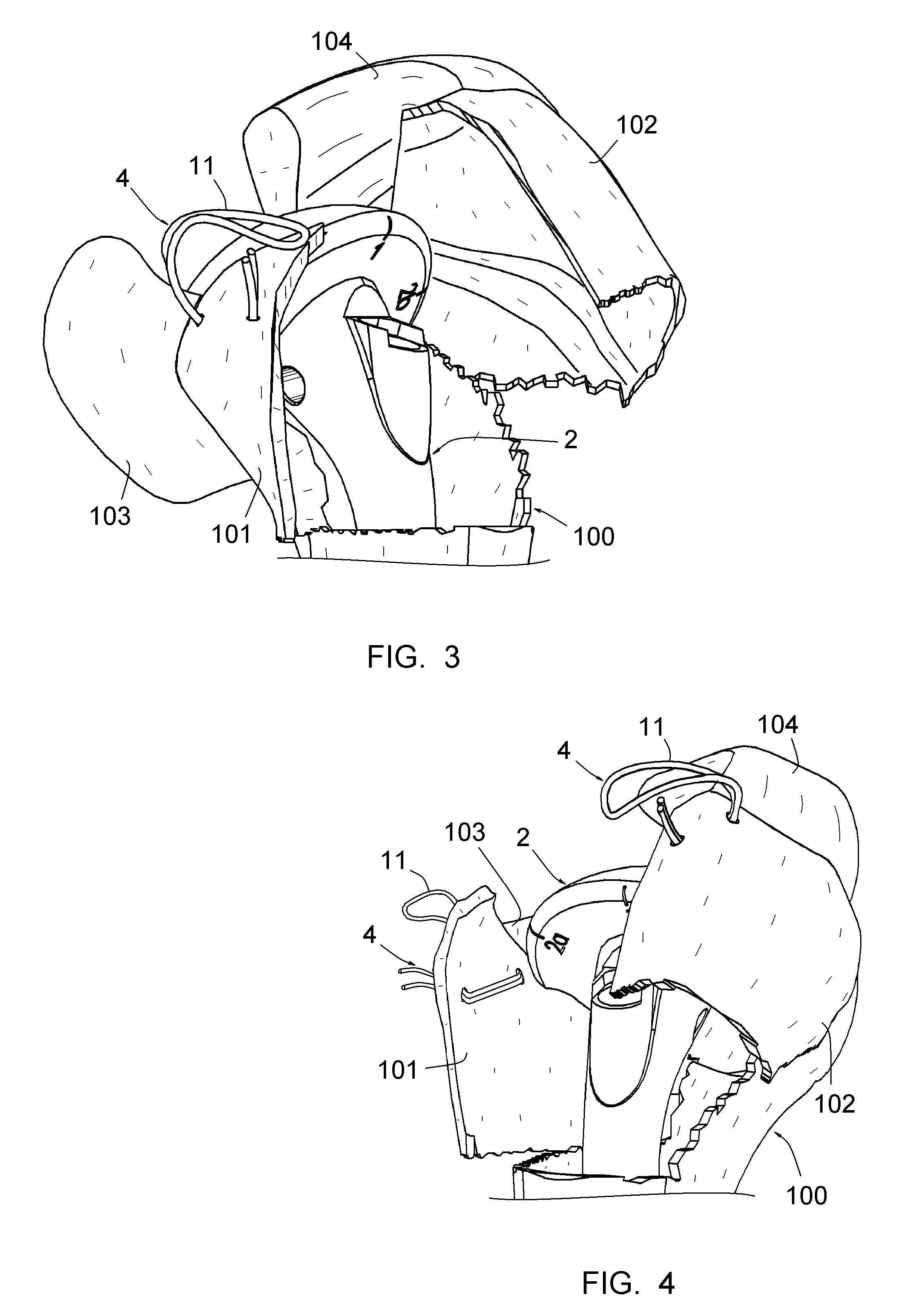
[0051]FIGS. 1 and 3 to 10 show the upper end of a fractured humerus 100, whereof the tuberosities (lesser 101 and greater 102 tuberosity of the humerus) are fractured and completely or partially separated from the rest of the bone. References 103 and 104 respectively designate the tendons of the subscapularis muscle, connected to the lesser tuberosity of the humerus 101, and the supraspinous muscle, connected to the greater tuberosity of the humerus 102.

[0052]The repair equipment comprises a humeral rod 2 and three types of subassemblies 3, 4, 5 with a needle and a looped thread.

[0053]The surgical method allowed by this equipment comprises steps for placing the humeral rod 2 and the assemblies 3, 4, 5 on the bone, described in reference to FIGS. 1 and 3 to 5 below; it then comprises steps for knotting the threads of the assemblies 4, 5, and placing and knotting the assembly 3, described in reference to FIGS. 6 to 10 below.

[0054]FIG. 1 shows that the humeral rod 2 is intended to be p...


PUM


Abstract

This method comprises the use of a repair equipment including a humeral rod (2) intended to be placed in the medullary cavity of the humerus, comprising at least one hole (6) for receiving a thread (11) for repositioning the tuberosities (101, 102) and for maintaining the latter with respect to the rest of the bone. Said hole (6) is formed in the metaphyseal portion of the humeral rod (2), in the anteroposterior direction thereof; and the repair equipment further comprises a so-called “guying” subassembly (3), to maintain the tuberosities (101, 102) when they re-installed, two second so-called “traction” subassemblies (4), for pulling of the tuberosities (101, 102) one toward the other, and two so-called third “pressing” subassemblies (5), for tackling the tuberosities (101, 102); each of these sub-assemblies comprises a needle and thread (11) connected to this needle, this thread (11) forming a loop.

Description

CROSS-REFERENCE TO RELATED APPLICATIONS[0001]This application claims the benefit of priority to U.S. Provisional Application No. 61 / 392,050 filed Oct. 12, 2010, the contents of which are incorporated herein by reference.BACKGROUND OF THE INVENTION[0002]The present invention relates to a surgical method for repairing a fractured shoulder joint.[0003]It is well known to repair a shoulder joint using a shoulder prosthesis comprising a humeral rod intended to be inserted into the medullary cavity of the humerus. This rod can receive a condyle (which can be either the reimplanted native bone head or a prosthetic head); in the case of a prosthetic head, the prosthesis also comprises a portion implanted on the shoulder blade, forming a corresponding glenoid.[0004]A fractured shoulder joint frequently involves a fracture of the tuberosities (lesser and greater tuberosities of the humerus), which must consequently be replaced on the prosthesis in precise and stable positions. Failing this, t...

Claims


Application Information

Patent Timeline
Patent Type & Authority Applications(United States)
IPC IPC(8): A61B17/58A61B17/04
CPCA61B17/0469A61B17/06A61B17/06166A61B17/56A61B17/72A61F2002/0882A61B2017/06028A61B2017/564A61F2/4059A61F2002/0847A61B17/842
Inventor MARTIN, JEAN-JACQUESLASCAR, TRISTANOBERT, LAURENT
Owner FX SOLUTIONS
Learn More