
System for Detecting Oil Spills and Method Thereof

a technology for oil spill detection and oil spill detection, applied in wave based measurement systems, instruments, reradiation, etc., can solve the problems of huge environmental disasters, more economic damage to fisheries or tourism, and a great human and physical effor

Inactive Publication Date: 2012-04-12
KOREA METEOROLOGICAL ADMINISTRATION
View PDF10 Cites 24 Cited by
  • Summary
  • Abstract
  • Description
  • Claims
  • Application Information

AI Technical Summary

Benefits of technology

[0008]According to an embodiment of the present disclosure, the embodiment may obtain reflectivity by a ratio of radiance observed from a satellite to estimated sea surface temperature and calculate two reflectivities using polarization properties of electromagnetic waves according to surface properties. In this case, physical properties of water are different from those of oil and the reflective index values of the water and the oil are different from each other, thereby detecting oil spills on the surface.
[0009]The exemplary embodiments of the present disclosure may detect how much oil is spreading by obtaining a refractive index and reflectivity polarization component of an oil band exposed on the sea surface.

Problems solved by technology

Oil spills on the sea cause environmental disaster near the waters, require a great human and physical effort for purification, and cause more economic damage to fisheries or tourism, etc.
In recent years, the oil spill off the Taean Peninsula in South Korea and the continuous spill due to the explosion at a deep sea oilfield in the Gulf of Mexico near the United States have caused huge environmental disasters.
The existing methods depending on satellite observation use various spectrums from ultraviolet to microwave bands, but have drawbacks in mainly detecting the oil spills in daytime only and a false signal.

Method used


Image

  • System for Detecting Oil Spills and Method Thereof
  • System for Detecting Oil Spills and Method Thereof
  • System for Detecting Oil Spills and Method Thereof

Examples


Embodiment Construction

[0019]Exemplary embodiments of the present disclosure will be described below in detail with reference to the accompanying drawings. Wherever possible, the same reference numerals will be used to refer to the same elements throughout the specification, and a duplicated description thereof will be omitted. It will be understood that although the terms “first”, “second”, etc. are used herein to describe various elements, these elements should not be limited by these terms. These terms are only used to distinguish one element from another element.

[0020]Aspects of the present disclosure may involve a detection method using a refractive index, i.e., a difference in material characteristic between water and oil to provide a method and a system for detecting oil spills using a satellite at night, which could not be solved by the existing methods.

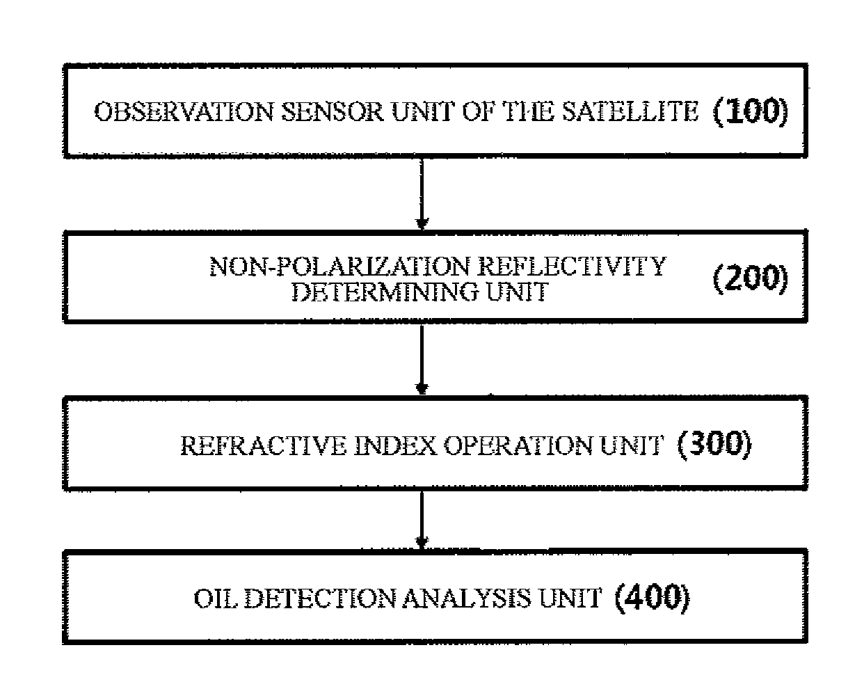
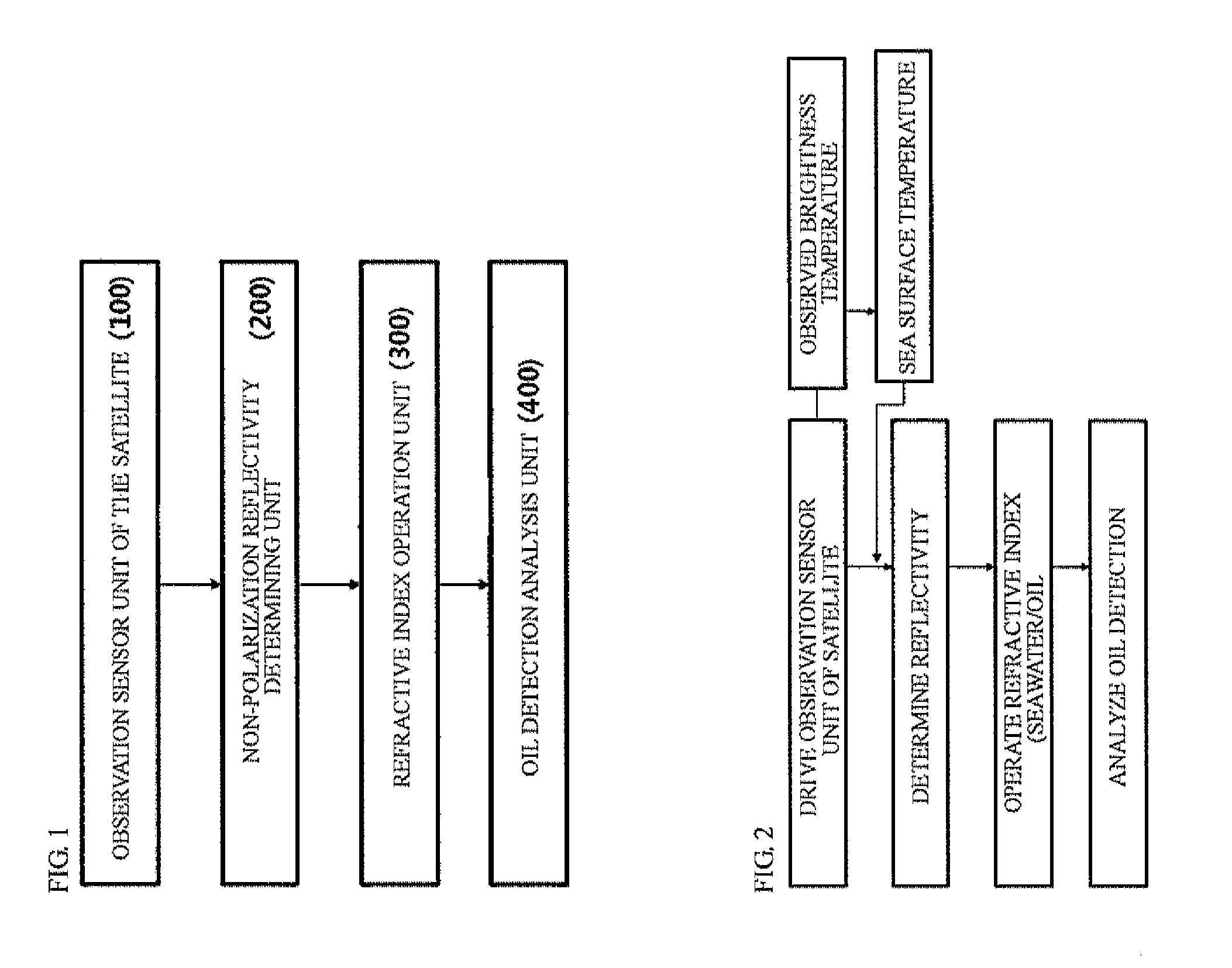
[0021]FIG. 2 shows a block diagram of a configuration of an oil detection system (hereinafter, referred to as ‘the present system’) detecting oil ...


PUM

PropertyMeasurementUnit
reflectivityaaaaaaaaaa
refractive indexaaaaaaaaaa
vertical reflectivityaaaaaaaaaa

Abstract

Disclosed are systems and methods of detecting oil spills on the sea surface at night. According to some embodiments, implementations herein involve detection of the polarized reflectivity and the refractive index of the water and the oil using the polarization properties of the electromagnetic waves based on satellite data to accurately and quantitatively detect the position of the oil band spread on the sea.

Description

CROSS-REFERENCE(S) TO RELATED APPLICATION[0001]This application claims priority of Korean Patent Application No. 10-2010-0098204, filed on Oct. 8, 2010, in the Korean Intellectual Property Office, which is hereby incorporated by reference in its entirety.BACKGROUND OF THE DISCLOSURE[0002]1. Field of the Disclosure[0003]The present disclosure relates to a system for detecting oil spills on the sea at night using refractive index calculation based on satellite observation, and a method thereof.[0004]2. Description of the Related Art[0005]Oil spills on the sea cause environmental disaster near the waters, require a great human and physical effort for purification, and cause more economic damage to fisheries or tourism, etc. Although it is possible to detect the oil band using aircraft, only a satellite method can be used for observing the whole oil band at the same time and detecting a change process in the oil band. There are various methods, using visible, ultraviolet, infrared spect...

Claims


Application Information

Patent Timeline
Patent Type & Authority Applications(United States)
IPC IPC(8): G06F19/00G01N33/26
CPCG01S13/88G01S7/499G01V8/00
Inventor HONG, SUNGWOOK
Owner KOREA METEOROLOGICAL ADMINISTRATION
Learn More