
Data deduplication

a data and data technology, applied in the field of data deduplication, can solve the problems of requiring a lot of network bandwidth, and achieve the effects of reducing the storage requirements of clients, reducing the complexity of implementation and management, and saving network bandwidth

Active Publication Date: 2012-04-12
FALCONSTOR
View PDF7 Cites 47 Cited by
  • Summary
  • Abstract
  • Description
  • Claims
  • Application Information

AI Technical Summary

Benefits of technology

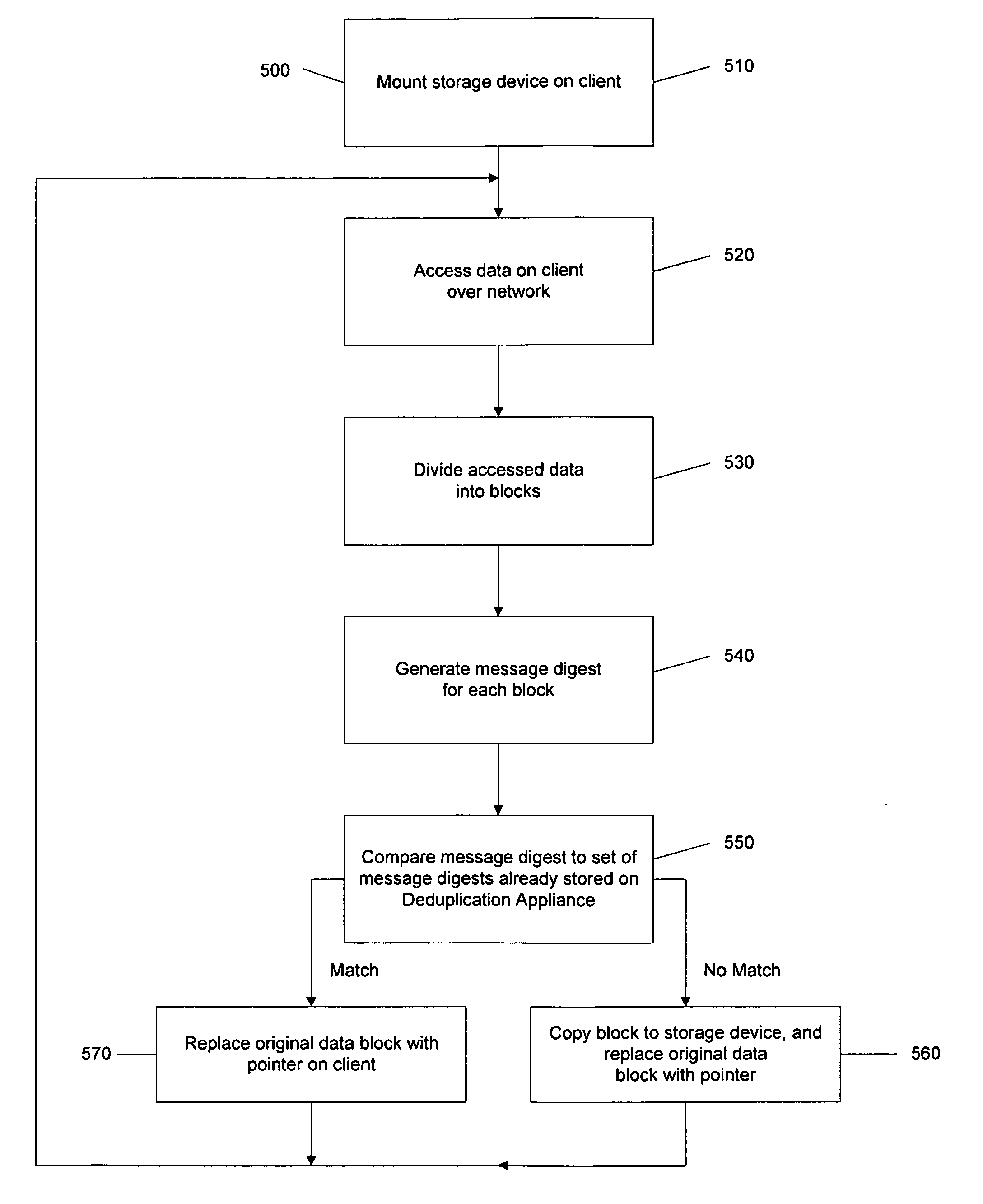
[0007]In accordance with a first embodiment of the invention, methods and systems are provided for proactively accessing data stored locally on a client computer over a network by a deduplication appliance for deduplication and storage without the need for the client to send the data to the deduplication appliance, thereby reducing the complexity of implementation and management of the deduplication appliance. In one example, a deduplication appliance mounts the one or more local storage devices of a client computer that are designated as network shared storage devices accessible to the deduplication appliance over a network, accesses data from the local storage devices, deduplicates the data, and stores unique data in storage controlled by the deduplication appliance. The deduplication appliance may initiate the access and deduplication of files from a network share on a client system, in accordance with rules, such as a deduplication schedule, established by the client machines. All the data to be deduplicated does not, therefore, have to be moved across the network to the deduplication appliance, saving network bandwidth. The deduplication appliance replaces the data on the client with indicators, such as pointers or symbolic links, to the corresponding stored data in the storage of the deduplication appliance, changing the file to a stub file. The file containing the data can also be replaced by one or more stub files containing the indicators. The client may access the deduplicated data files by transparently accessing the location of the data on the deduplication appliance indicated by the stub file, thereby reducing storage requirements of the client.
[0011]In accordance with a second embodiment of the invention, a functionality is implemented on a client system to manage requests to copy files of deduplicated data stored on a deduplication appliance, where the destination location is also on the deduplication appliance, without moving or copying actual data. Such copying is commonly used in data management operations, for example. In one example, when it is desired to copy a data file that has been deduplicated and is now represented by a stub file in a first location, a command, referred to herein as “dcopy,” may be implemented to create on the client an additional stub file containing an indicator to the location of the data on the deduplication appliance's storage, at the desired second location. This eliminates the need to actually copy the data and provide the data to the client. Time, network bandwidth, and CPU usage in both the client and deduplication appliance are thereby saved.

Problems solved by technology

This is cumbersome, and may require use of a lot of network bandwidth and CPU usage in the client and the deduplication appliance.

Method used


Image

  • Data deduplication
  • Data deduplication
  • Data deduplication

Examples


first embodiment

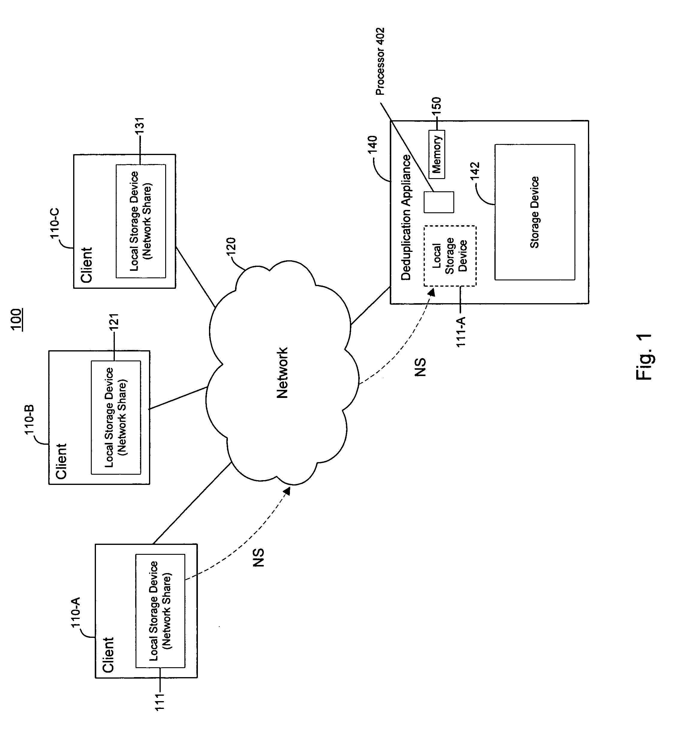
[0031]In accordance with the invention, the deduplication appliance 140 accesses data located on the local storage devices 111, 121, and 131 via the network 120, deduplicates the data, and stores the deduplicated data in the storage device 142. To enable access to the data on the local storage devices 111, 121, and 131, the deduplication appliance 140 mounts the network share local storage devices 111, 121, and 131 or a portion thereof. Mounting the network share local storage devices 111, 121, and 131 provides access to the data on the local storage device, as if the local storage device were present in the deduplication appliance or directly connected to it. This is shown schematically in FIG. 1, where a storage device 111-A corresponding to the local storage device 111 of the client machine 110-A is shown in phantom in the deduplication appliance 140. While FIG. 1 shows the entire local storage device 111 as a network share, only a portion of the local storage device may be desig...

second embodiment

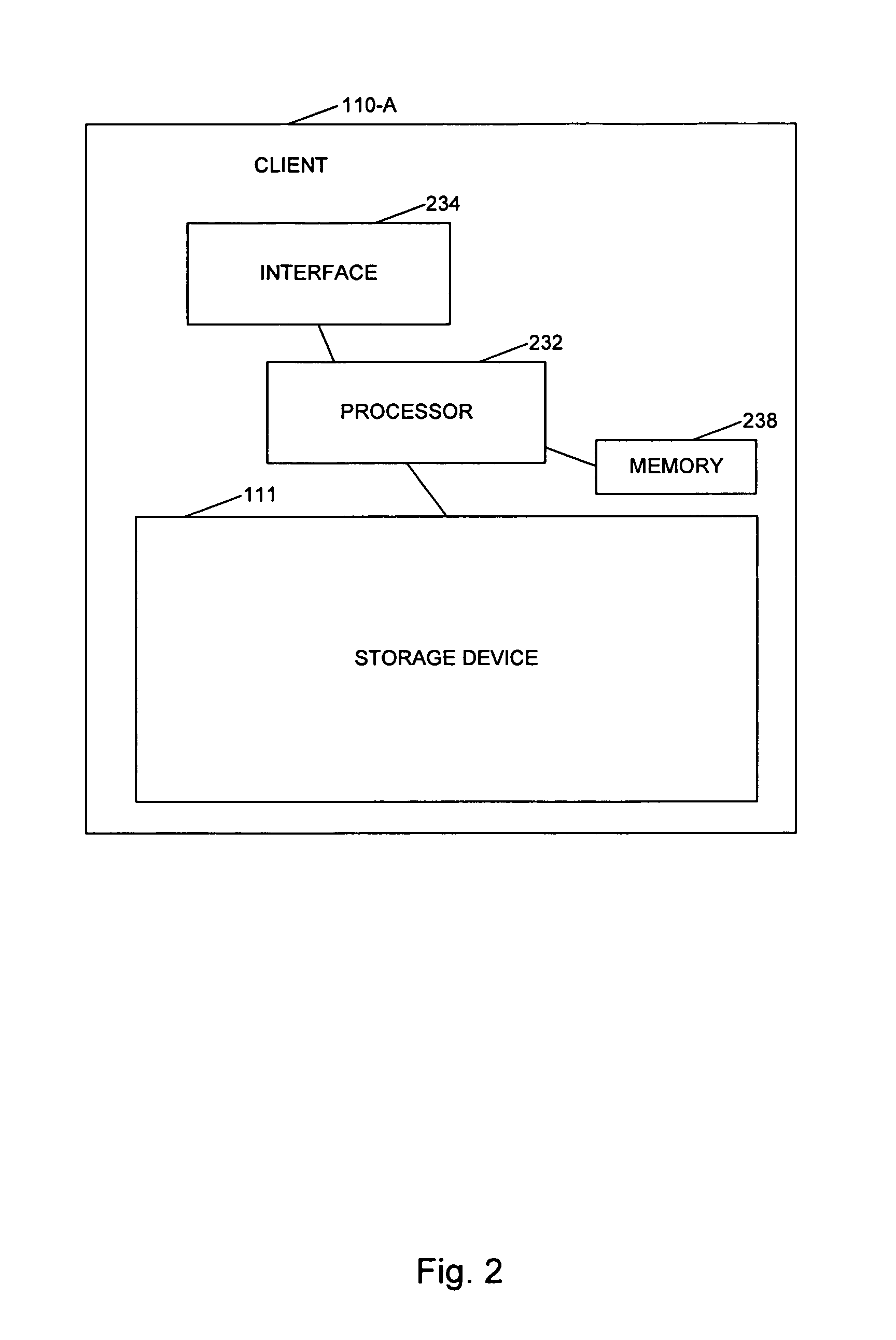
[0062]FIG. 9 is an example of a routine 600 for implementing the invention. A command to copy a file to a location is received by the processor 232 of the client machine 110-A from a user, in step 610. It is determined by the processor 232 whether the file to be copied has a source and destination in the deduplication appliance 140 by the processor 232, via the agent, plug-in module, or kernel, for example.

[0063]If it is determined that the file does have a source and destination on the deduplication appliance 140, then dcopy is invoked to copy the stub file in the first location containing the indicator or indicators to the location of the file to be copied on the deduplication appliance 140, to the second location, by the agent, plug-module, or kernel.

[0064]If the file source and location are not on the deduplication appliance 140, then standard copying is performed by the processor 232.


PUM


Abstract

A method of deduplicating data is disclosed comprising mounting, by a deduplication appliance, network shared storage of a client machine, via a network, accessing data to be deduplicated on the network shared storage device, deduplicating the data, storing the deduplicated data on a second storage device, and replacing the data in the network shared storage device by at least one indicator of the location of the deduplicated data in the second storage device. A method is also disclosed for copying deduplicated data stored by a deduplication appliance, by a client machine, comprising receiving a request to copy data from a first location to a second location, by the client machine, by providing at least one second indicator to the third location on the deduplication appliance, at the second location, if the source and the destination are on the deduplication appliance. Systems are also disclosed.

Description

RELATED APPLICATION[0001]The present application claims the priority of U.S. Provisional Patent Application No. 61 / 402,535, which was filed on Aug. 31, 2010, is assigned to the assignee of the present application, and is incorporated by reference herein.BACKGROUND OF THE INVENTION[0002]Data deduplication reduces storage requirements of a system by removing redundant data, while preserving the appearance and the presentation of the original data. For example, two or more identical copies of the same document may appear in storage in a computer and may be identified by unrelated names. Normally, storage is required for each document. Through data deduplication, the redundant data in storage is identified and removed, freeing storage space for other data. Where multiple copies of the same data are stored, the reduction of used storage may become significant. Portions of documents or files that are identical to portions of other documents or files may also be deduplicated, resulting in ...

Claims


Application Information

Patent Timeline
IPC IPC(8): G06F17/30
CPCG06F17/30159G06F16/1752
Inventor LAM, WAYNE
Owner FALCONSTOR
Learn More