Driving system for railroad vehicle

a technology for driving systems and railroads, applied in the direction of locomotives, battery/cell propulsion, transportation and packaging, etc., can solve the problems of no means for rail cars, no regenerative energy reuse, etc., and achieve the effect of high mobility

Inactive Publication Date: 2012-04-19
HITACHI LTD
View PDF3 Cites 20 Cited by
  • Summary
  • Abstract
  • Description
  • Claims
  • Application Information

AI Technical Summary

Benefits of technology

[0020]The present invention can provide a high mobility railroad vehicle system that can reciprocally carry out through operation between a non-electrified section and an electrified section without installing new facilities such as oil supply equipment in the electrified section and without considering distinction between the non-electrified section and the electrified section.

Problems solved by technology

However, the diesel railcar does not include means, such as trolley wire, for transferring energy to other vehicles, and there is no reuse of regenerative energy as in the electric railroad vehicle.

Method used


Image

  • Driving system for railroad vehicle
  • Driving system for railroad vehicle
  • Driving system for railroad vehicle

Examples


embodiment

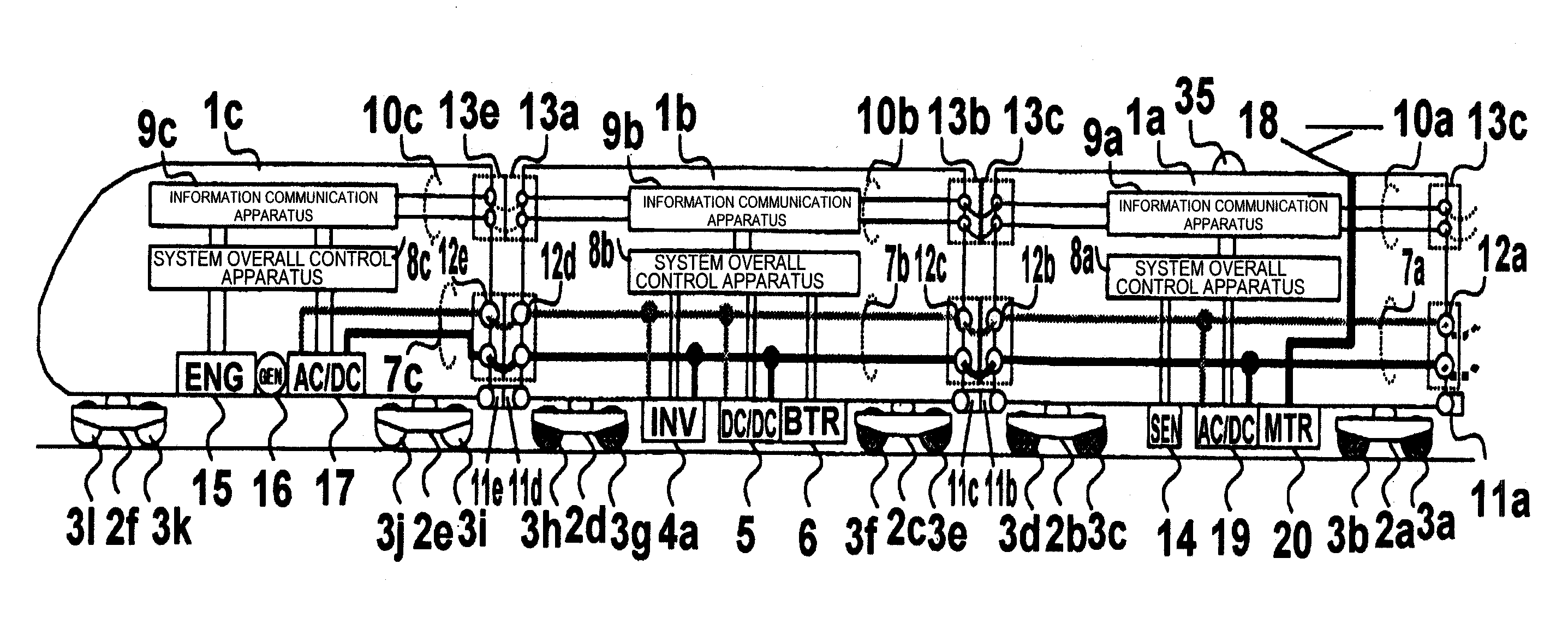
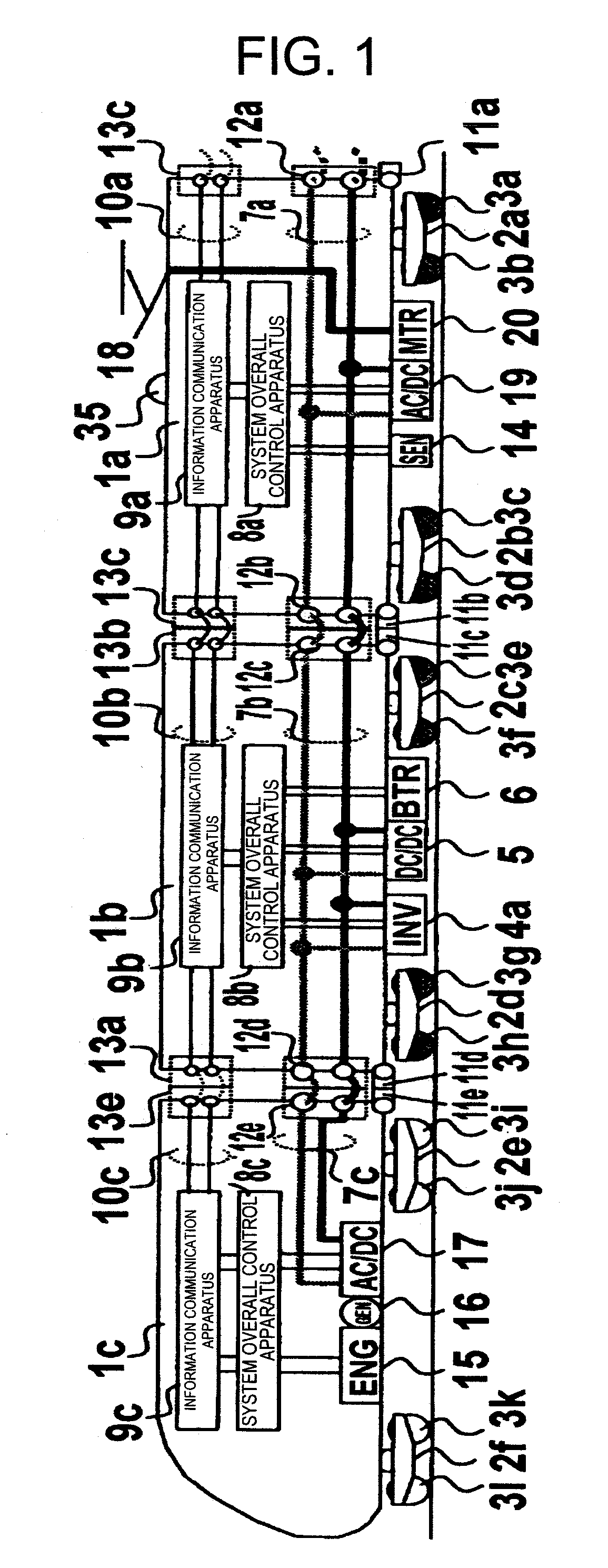
[0029]FIG. 1 is a diagram showing a device configuration of an embodiment in a driving system for railroad vehicle of the present invention.

[0030]Vehicles 1a, 1b, and 1c are parts of the vehicles constituting the train formation. A third vehicle 1a includes inter-vehicle couplers 11a and 11b. A second vehicle 1b includes inter-vehicle couplers 11c and 11d. A lead vehicle 1c includes inter-vehicle couplers 11e and 11f. The vehicle 1a and the vehicle 1b are connected through the inter-vehicle coupler 11b and the inter-vehicle coupler 11c, and the vehicle 1b and the vehicle 1c are connected through the inter-vehicle coupler 11d and the inter-vehicle coupler 11e.

[0031]The vehicle 1a is supported, on rail surfaces not shown, by wheel and axle 3a and 3b through a truck 2a and by wheel and axle 3c and 3d through a truck 2b. The vehicle 1b is supported, on the rail surfaces not shown, by wheel and axle 3e and 3f through a truck 2c and by wheel and axle 3g and 3h through a truck 2d. The veh...


PUM


Abstract

Provided is a high mobility railroad vehicle system configured to reciprocally carry out a direct drive between a non-electrically driven section and an electrically driven section without installing new facilities such as oil supply equipment and without considering distinction between the non-electrically and electrically driven sections. A railroad vehicle system is provided with an overall control apparatus to respectively control an external electric power supply means, an internal electric power supply means, an electricity storage means, electric power conversion means and a motor driving means. The railroad vehicle system judges or previously notifies as to whether the present driving railroad section is the electrically driven section or non-electrically driven section in accordance with driving position information received from a position information generation means such as a ground facility on a railroad equipped outside of the vehicle and a global positioning system (GPS). The system cuts off from an external electric power source in the non-electrically driven section and carries out a smooth shifting control in order to connect to the external electric power source in the electrically driven section.

Description

TECHNICAL FIELD[0001]The present invention relates to a driving system for railroad system, and particularly, to a technique for installing external electric power supply means, electricity generation means, and electric power storage means and using electric power obtained by the means to drive a railroad vehicle.Background Art[0002]Iron wheels roll over rail surfaces to drive a railroad vehicle, and the railroad vehicle is characterized by small running resistance compared to an automobile. Particularly, in a recent electric railroad vehicle, a main motor is operated as an electricity generator during braking to obtain braking force. At the same time, regenerative brake control is performed in which the electric energy generated by the main motor is returned to the trolley wire to reuse the electric energy as powering energy of other vehicles. The electric railroad vehicle with the regenerative brake can travel by about half the energy consumption compared to an electric railroad ...

Claims


Application Information

Patent Timeline
Patent Type & Authority Applications(United States)
IPC IPC(8): B61C3/00B60L11/00B60L11/18B60L9/02B60L50/10B60L50/15
CPCB61C3/02B61C7/04Y02T30/12Y02T30/16B60L7/16B60L9/00Y02T10/70B60L11/1801Y02T10/7005Y02T10/7077B60L9/28B60L2260/26B60L2200/26B60L11/02B60L50/53B60L50/10Y02T30/00Y02T10/7072B60L13/00B61C9/24
Inventor SHIMADA, MOTOMIKANEKO, TAKASHIMOCHIZUKI, KENTOISHIDA, SEIJI
Owner HITACHI LTD
Why Eureka
Try Eureka