Rail storage system

a storage system and rail technology, applied in the field of rail storage systems, can solve the problems of inability to secure the attachment mechanism of accessories to the rail, accidental disengagement of accessories from the rail, and inability to secure the attachment mechanism, etc., to achieve the effect of adding strength and rigidity to the latch

Inactive Publication Date: 2012-04-19
RUBBERMAID
View PDF19 Cites 20 Cited by
  • Summary
  • Abstract
  • Description
  • Claims
  • Application Information

AI Technical Summary

Benefits of technology

[0003]The support may be dimensioned to extend from an upper edge of the rail to beyond the lower edge of the rail. The support may have a hook that engages the upper edge of the rail where the accessory is suspended on the rail by the hook. A flange may extend below the rail and be dimensioned such that the flange abuts or lies closely adjacent to the surface when the accessory is mounted on the rail. The gripper mechanism may comprise a latch engageable with an engagement mechanism on the rail. A spring may bias the latch toward the engagement mechanism. The latch may be positioned opposite to the engagement mechanism when the accessory is mounted on the rail. The latch may include a first cam surface that is disposed opposite a second cam surface on the engagement mechanism such that the engagement of the first cam surface with the second cam surface rotates the latch relative to the support. When a distal end of the latch clears the engagement mechanism, the latch is biased into engagement with the engagement mechanism. The latch may comprise a first mating surface that engages and grips a second mating surface on the engagement mechanism. A reinforcement member may be used to add strength and rigidity to the latch. The reinforcement member may be insert molded in the gripper mechanism and the reinforcement member may be exposed on a front surface of the gripper mechanism

Problems solved by technology

One issue with such rail storage systems results from not having a secure mechanism to attach the accessories to the rail.
When a consumer removes an item from an accessory, the accessory can be accidentally disengaged from the rail and remain entangled with the consumer's item.
This issue often arises with articles that wrap underneath the accessory.
If the article hits the bottom of the accessory, the upward force applied to the bottom of the accessory may result in the inadvertent disengagement of the accessory from the rail.

Method used


Image

  • Rail storage system
  • Rail storage system
  • Rail storage system

Examples


Embodiment Construction

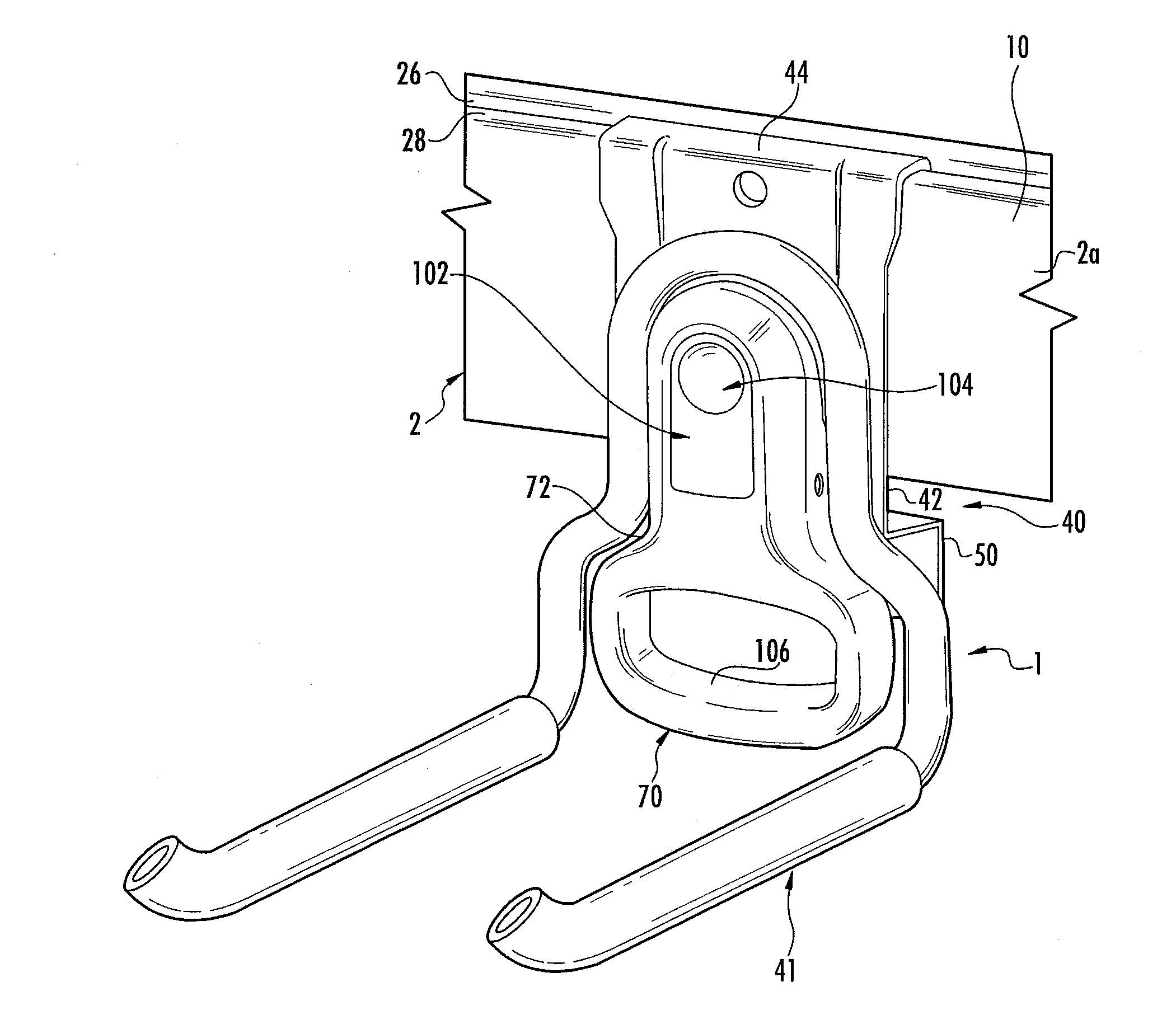
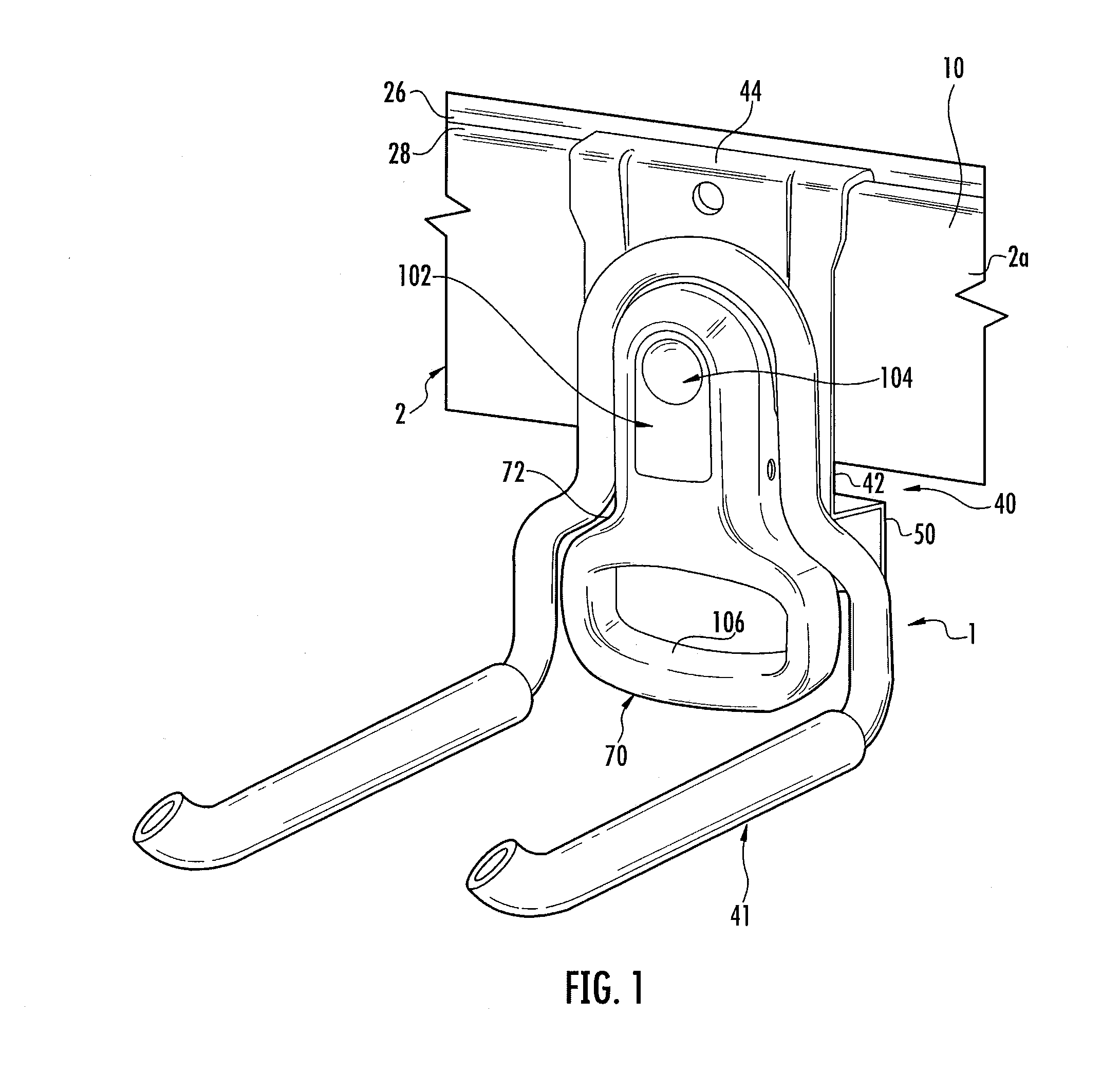
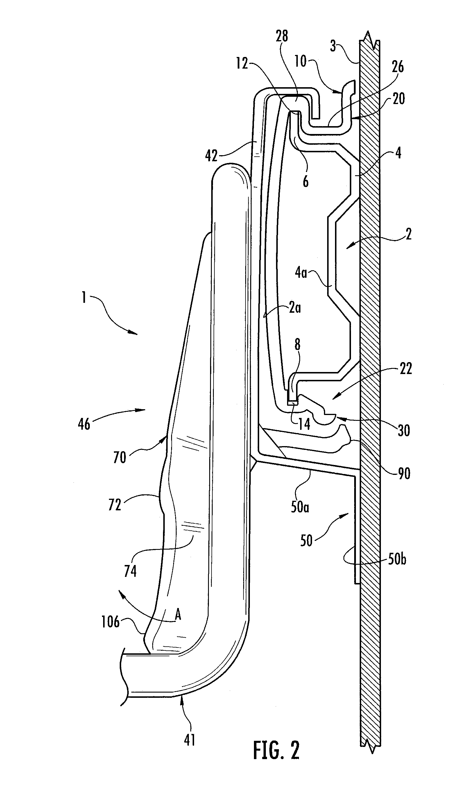
[0017]The accessory 1 will be described with reference to the rail 2, an embodiment of which is shown in FIGS. 1 and 2. While a specific embodiment of the rail is shown the accessory of the invention may be used with other rail configurations. Rail 2 extends along and is mounted to a vertical surface 3 such as a wall and may extend for an extended linear distance along the wall. In one embodiment the rail 2 is manufactured and sold in four to seven foot lengths although the rail may have any suitable length. Rail 2 may include a rail member 4 mounted to a wall or other vertical surface 3. The rail member 4 is made of steel or other rigid material and may include apertures for receiving fasteners such as screws for attaching the rail member 4 to the vertical surface 3. The rail member 4 includes a first flange 6 that extends along substantially the entire length of the upper edge of the rail member 4 and a second flange 8 that extends along substantially the entire length of the lowe...


PUM

PropertyMeasurementUnit
lengthaaaaaaaaaa
rigidityaaaaaaaaaa
areaaaaaaaaaaa

Abstract

A storage apparatus comprises a rail adapted to be secured to a surface and an accessory releasably mounted to the rail. The accessory comprises a gripper assembly and a storage device, the gripper assembly includes a gripper mechanism that is movably mounted relative to a support such that the gripper mechanism is movable into and out of engagement with the rail when the accessory is mounted on the rail.

Description

BACKGROUND[0001]Rail storage systems typically comprise a wall mountable rail, and accessories that connect to the rail. Such systems may be used in a garage or other similar area. The accessories are designed to hold a wide variety of consumer items such as tools, bicycles, hoses, sports equipment and other consumer articles. One issue with such rail storage systems results from not having a secure mechanism to attach the accessories to the rail. When a consumer removes an item from an accessory, the accessory can be accidentally disengaged from the rail and remain entangled with the consumer's item. This issue often arises with articles that wrap underneath the accessory. If the article hits the bottom of the accessory, the upward force applied to the bottom of the accessory may result in the inadvertent disengagement of the accessory from the rail.SUMMARY OF THE INVENTION[0002]The storage apparatus comprises a rail adapted to be secured to a surface and an accessory releasably mo...

Claims


Application Information

Patent Timeline
Patent Type & Authority Applications(United States)
IPC IPC(8): A47F5/00B23P19/04
CPCA47B96/067Y10T29/49826F16B12/38A47F5/0838
Inventor GREGORY, MICHAELWARNER, JR., ROBERT J.
Owner RUBBERMAID
Why Eureka
Try Eureka