Solar cell charging control

a solar cell and charging control technology, applied in the direction of secondary cell charging/discharging, electric vehicles, electrical apparatus, etc., can solve the problems of reducing the charge of the battery rather than an increase of the charge, and the load will not provide a meaningful measure of when the solar radiation is generated, so as to minimize the load of at least one solar cell in order to measure the output power of the battery

Inactive Publication Date: 2012-04-19
TECHTIUM
View PDF19 Cites 20 Cited by
  • Summary
  • Abstract
  • Description
  • Claims
  • Application Information

AI Technical Summary

Benefits of technology

[0025]Additional implementations of these methods can incorporate the step of disposing a switch to control the connection of the load to the at least one solar cell. The switch may be closed when the at least one solar cell is outputting power above the predetermined level, and it may be actuated by the control circuitry. Additionally, the switch may be closed only periodically, and according to another exemplary implementation of these methods, this periodic closing of the switch may be such that loading of the at least one solar cell in order to measure its output power, is minimized. The switch may be an electronically gated switch, such as a field effect transistor. Additionally, the load may be a resistive load.

Problems solved by technology

Without such a system, under low incident solar radiation conditions, the current required to power the charging circuits would be drawn from the internal battery of the device, resulting in reduction of the battery charge rather than an increase of its charge from the solar input.
If the load is designed such that the load current with minimal solar radiation is much less than that level, the load will not provide a meaningful measure of when the solar radiation is sufficient to power the charging circuits.
If the loading current is much more than that level, the load will waste power available from the solar cell, diverting it from use within the true load, such as the device which it is meant to be powering and its internal battery which it is meant to be charging.

Method used


Image

  • Solar cell charging control
  • Solar cell charging control
  • Solar cell charging control

Examples


Embodiment Construction

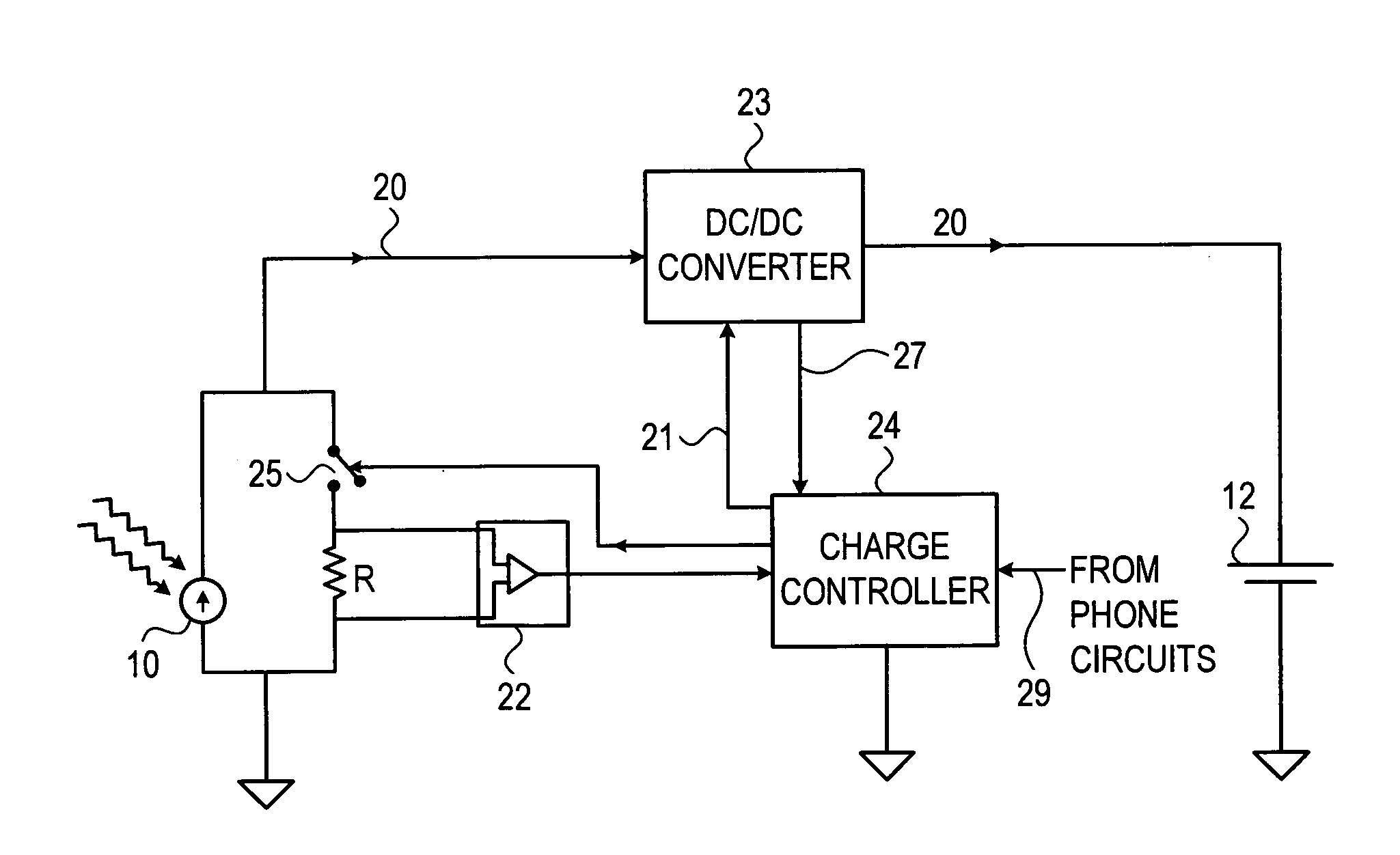
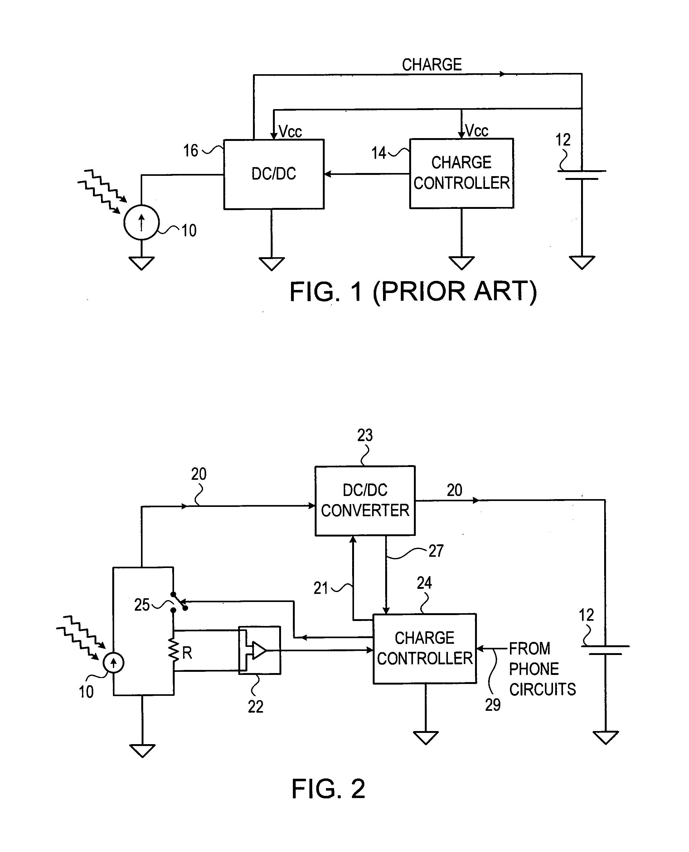
[0033]Reference is now made in FIG. 1, which is a schematic diagram of a prior art solar cell 10 charging circuit, for charging the internal battery 12, of a mobile device, such as a cellular phone. A cellular phone is used as the example in the implementations shown in all of this section, though it is to be understood that the invention is not meant to be limited thereto. Although this circuit shows only a solar cell charger, it is to be understood that there could also be additional inputs from external voltage sources, which could use the same charging circuitry as the solar cell, or dedicated charging circuitry. This is applicable not only to the implementation of FIG. 1 but to all the other implementations shown in this disclosure. The battery 12 not only powers the operative circuits of the mobile device, but it also supplies power to the charge controller 14 of the mobile device, and to the DC-DC converter 16 used to up-convert the voltage from the solar cell to a level suit...


PUM


Abstract

To prevent the battery of a solar charged device from discharge when insufficient solar radiation is present, a control circuit is provided to disable the charging circuits under those conditions. A current load is applied to the output of the solar cell, and the level of power drawn by this load from the solar cell is measured. Control circuits disable the charging circuits of the device when the signal from the current monitor indicates that insufficient solar power is detected. The monitor current load should be such that the power drawn by it should be at least of the same order as the power required by the charging circuitry for its quiescent operation. A series switch may be used so that current is drawn through the load only when solar output is sufficient to enable charging. Alternatively, a periodically pulsed switch may be used to limit the load current.

Description

FIELD OF THE INVENTION[0001]The present invention relates to the field of solar cell power sources for providing load current to a device, and especially to control of the current drawn from the solar cell so as to avoid depletion of the internal batteries of the mobile device.BACKGROUND OF THE INVENTION[0002]Solar cells have a number of characteristics which are important in order to optimize their efficiency in charging mobile devices. Because of the space and weight premium on a mobile device such as a cellular phone, both the solar cell and the battery are generally made as small and light as possible. As a result, the power budget of the charging and battery system is critical, and every effort must be made to ensure optimum efficiency in the use of these components. Therefore, it is important that no energy be wasted by powering circuits when there is no need for their function.[0003]There exists a potential problem with the charging of batteries of mobile devices using solar ...

Claims


Application Information

Patent Timeline
Patent Type & Authority Applications(United States)
IPC IPC(8): H02J7/00
CPCH02J7/35
Inventor MANOR, DRORBREITING, DANIEL
Owner TECHTIUM
Why Eureka
Try Eureka