Liquid crystal display

Inactive Publication Date: 2012-04-19
CHUNGHWA PICTURE TUBES LTD
View PDF5 Cites 12 Cited by
  • Summary
  • Abstract
  • Description
  • Claims
  • Application Information

AI Technical Summary

Benefits of technology

[0009]Therefore, the main object of the present invention is to provide an LCD capable of improving its aperture ratio to solve problems occurring in the prior art. The present invention can not only overcome the limit of manufacturing precision but also increase brightness as well as reduce manufacturing costs.

Problems solved by technology

The larger the gap d1 is, the smaller the aperture ratio of a pixel and the smaller the transmission ratio become, further increasing the cost of the conventional TFT array panel 10.

Method used


Image

  • Liquid crystal display
  • Liquid crystal display
  • Liquid crystal display

Examples


first embodiment

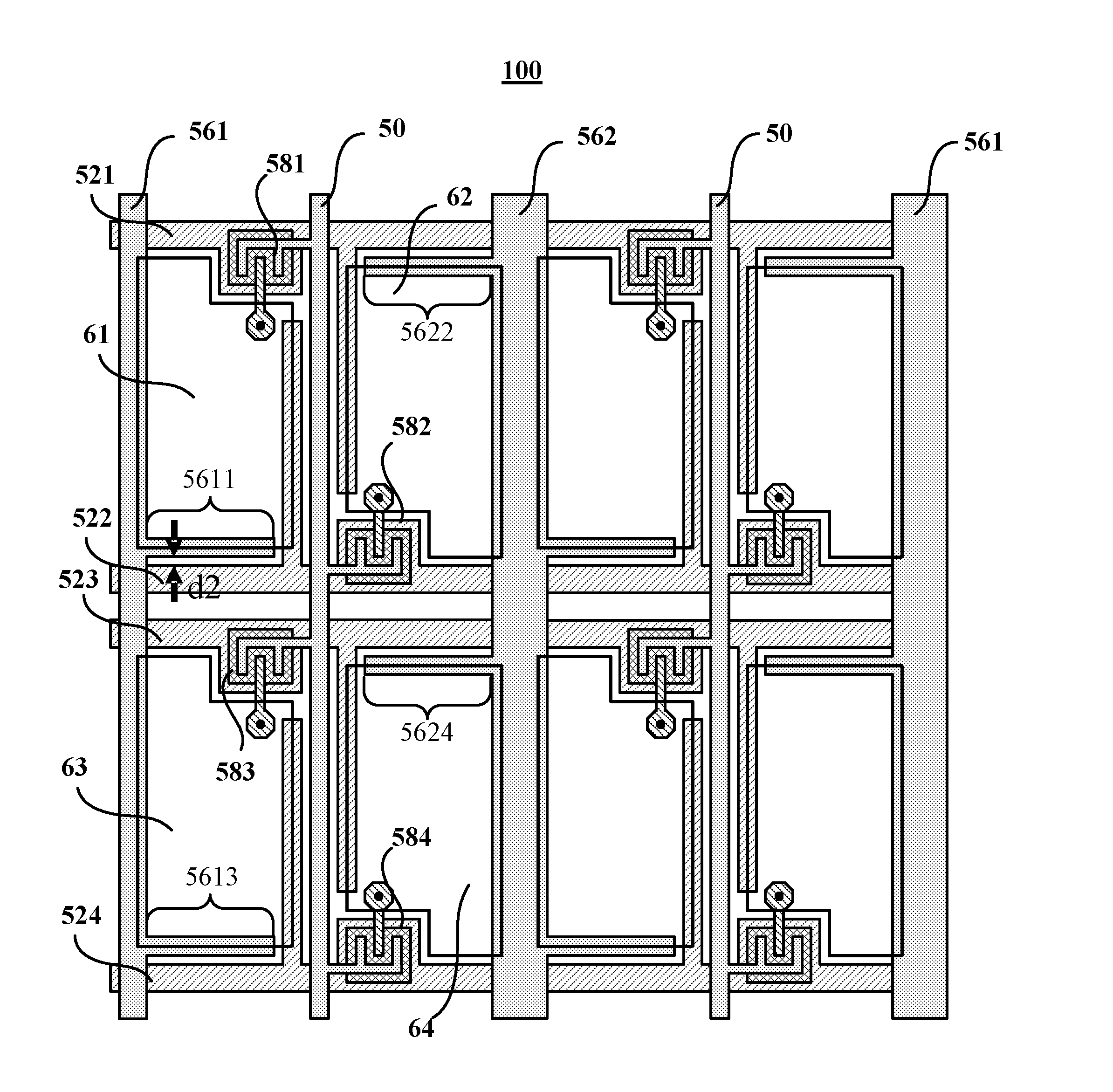
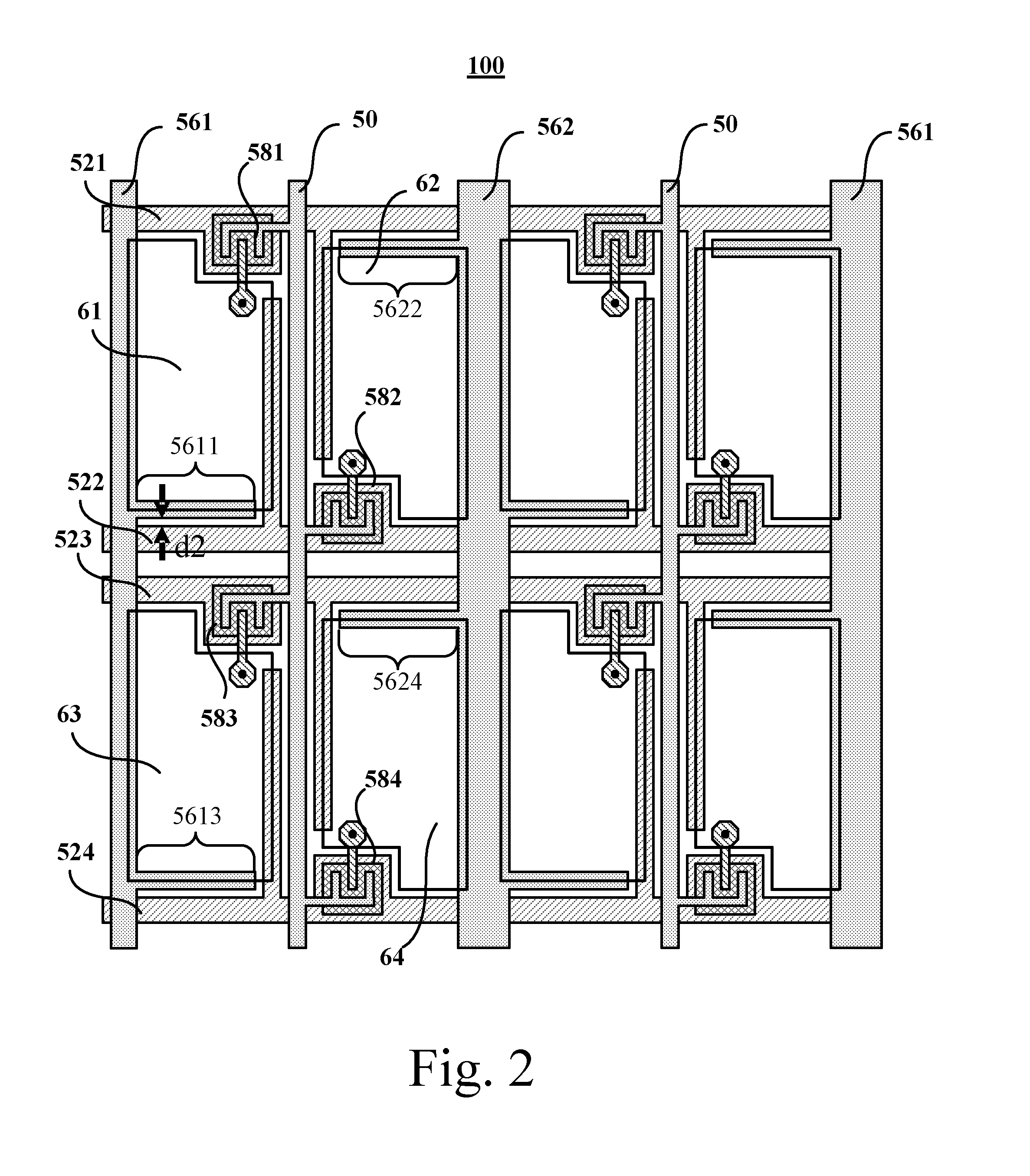
[0025]Refer to FIG. 2, which is a layout of a TFT array panel 100 according to the present invention. The TFT array panel 100 used in an LCD comprises a first pixel electrode 61, a second pixel electrode 62, a third pixel electrode 63, a fourth pixel electrode 64, a first scan line 521, a second scan line 522, a third scan line 523, a fourth scan line 524, a data line 50, transistors 581-584, a first storage capacitor electrode line 561, and a second storage capacitor electrode line 562.

[0026]The first pixel electrode 61 is electrically connected to the first scan line 521 and the data line 50 via the transistor 581. The second pixel electrode 62 is electrically connected to the second scan line 522 and the data line 50 via the transistor 582. The third pixel electrode 63 is electrically connected to the third scan line 523 and the data line 50 via the transistor 583. The fourth pixel electrode 64 is electrically connected to the fourth scan line 524 and the data line 50 via the tra...

second embodiment

[0031]Refer to FIG. 3, which shows a layout of a TFT array panel 200 according to the present invention. Differing from the TFT array panel 100, the TFT array panel 200 has a connection line 57 between the extension line 5611 and the extension line 5624. Owing to the connection line 57, the storage capacitor electrode lines 561 and 562 are less influenced by capacitive coupling effects caused by other signals, which solves a crosstalk problem and further improves display quality of the TFT array panel 200.

third embodiment

[0032]Please refer to FIG. 4 showing a layout of a TFT array panel 300 according to the present invention. A first storage capacitor electrode line 561 of the TFT array panel 300 further comprises a first storage capacitor electrode extension line 5611 extended toward the data line 50 from the first storage capacitor electrode line 561. The second storage capacitor electrode line 562 further comprises a second storage capacitor electrode extension line 5622 extended toward the data line 50 from the second storage capacitor electrode line 562. The first storage capacitor electrode line 561 further comprises a third storage capacitor electrode extension line 5613 extended toward the data line 50 from the first storage capacitor electrode line 561. The second storage capacitor electrode line 562 further comprises a fourth storage capacitor electrode extension line 5624 extended toward the data line 50 from the second storage capacitor electrode line 562. According to the present embodi...


PUM


Abstract

An LCD includes a first pixel electrode coupled to a first scan line and a data line, and a second pixel electrode coupled to a second scan line and the data line. A first and a second storage capacitor electrode lines are at two sides of the data line and across the scan lines. A first storage capacitor electrode extension line is extended out of the first storage capacitor electrode line and toward the data line, and a second storage capacitor electrode extension line is extended out of the second storage capacitor electrode line and toward the data line. The first pixel electrode and second pixel electrode partly overlap the first and the second storage capacitor electrode extension lines, respectively. Since the storage capacitor electrode line and the scan line is formed on different metal layer, a gap between the storage capacitor electrode line and the scan line is shortened.

Description

RELATED APPLICATIONS[0001]This application claims priority to Taiwan Patent Application Serial Number 099135330, filed on Oct. 15, 2010, which is herein incorporated by reference.BACKGROUND OF THE INVENTION[0002]1. Field of the Invention[0003]The present invention relates to a liquid crystal display (LCD), and more particularly, to an LCD capable of improving its aperture ratio.[0004]2. Description of Prior Art[0005]An advanced monitor with multiple functions is an important feature for use in current consumer electronic products. Liquid crystal displays (LCDs) which are colorful monitors with high resolution are widely used in various electronic products such as monitors for mobile phones, personal digital assistants (PDAs), digital cameras, laptop computers, and notebook computers.[0006]An LCD comprises two substrates having electrodes and a liquid crystal (LC) layer between the two substrates. Voltage is applied on the electrodes so the LC molecules inside the LC layer are reorie...

Claims


Application Information

Patent Timeline
IPC IPC(8): G09G3/36G06F3/038
CPCG09G3/3648G09G2300/0465G02F2201/40G02F1/136286G02F1/136213
Inventor LIN, YEN-FENTSAI, YI-CHENG
Owner CHUNGHWA PICTURE TUBES LTD
Why Eureka
Try Eureka