
Joint carrier phase estimation and forward error correction

a carrier phase and forward error technology, applied in the field of fiber optic communication systems, can solve the problems of data stream integration, difficulty in distinguishing between binary digits (i.e. zeros) in data streams,

Inactive Publication Date: 2012-04-19
SUBCOM LLC
View PDF11 Cites 18 Cited by
  • Summary
  • Abstract
  • Description
  • Claims
  • Application Information

AI Technical Summary

Problems solved by technology

One problem associated with optical communications systems is the integrity of the data being communicated, particularly when optical signals are transmitted over long distances in long-haul communication systems such as, for example, undersea fiber optic cable systems.
Accumulated noise contributed by many different sources in a transmission path may cause difficulty in differentiating between the binary digits (i.e., the ones and zeros) in a data stream.
The performance of the Mth power scheme, however, is limited by the required differential coding.
The decision feedback scheme requires training and induces a feedback delay in the CPE.
The decision feedback scheme may also induce error propagation which may cause CPE failure.
However, implementing differential coding induces a receiver sensitivity penalty.

Method used


Image

  • Joint carrier phase estimation and forward error correction
  • Joint carrier phase estimation and forward error correction
  • Joint carrier phase estimation and forward error correction

Examples


Embodiment Construction

[0019]The present disclosure will now be described more fully hereinafter with reference to the accompanying drawings, in which preferred embodiments are shown. This disclosure, however, may be embodied in many different forms and should not be construed as limited to the embodiments set forth herein. Rather, these embodiments are provided so that this disclosure will be thorough and complete, and will fully convey the scope of the invention to those skilled in the art. In the drawings, like numbers refer to like elements throughout.

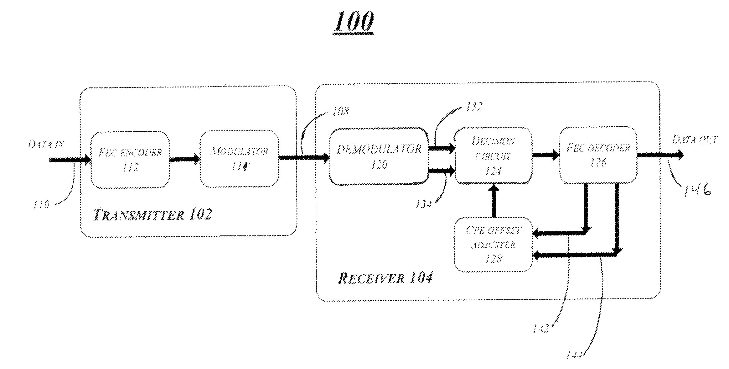
[0020]FIG. 1 shows an optical communication system 100 including an apparatus and method for a FEC aided CPE scheme consistent with one embodiment of the present invention. The system is capable of resolving M-fold phase ambiguity and / or error propagation problems by FEC decoding without the use of differential coding. Although exemplary embodiments are described in the context of an optical system, the broad concepts discussed herein may be implemented ...


PUM


Abstract

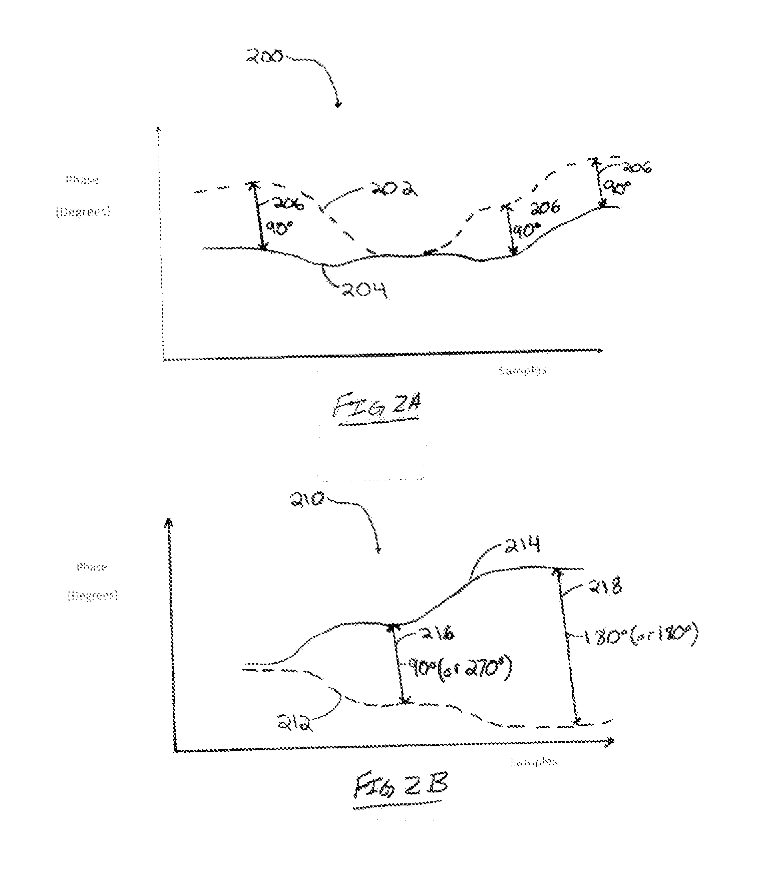
Methods and systems for processing an optical signal in a communication system are disclosed. The disclosed methods yield benefits for estimation and tracking of carrier phase of received signals at a digital coherent receiver without the use of differential coding. Specifically, phase ambiguity is removed by calculating the slope of the CPE at a location where the CPE begins to lose track of the received carrier phase signal. As such, a CPE offset adjustment may be applied in accordance with the calculated slope to reduce the number of ones and zeros corrected by a FEC decoder. Thus, the FEC aided CPE scheme may be a feed forward scheme that requires no training.

Description

FIELD OF THE INVENTION[0001]Embodiments of the present disclosure relate to the field of fiber optic communication systems. More particularly, the present disclosure relates to long haul fiber optic communication systems utilizing forward error correction (FEC) with joint carrier phase estimation (CPE).DISCUSSION OF RELATED ART[0002]In optical communication systems, an optical signal may be modulated with digital data in order to transmit the data over an optical transmission path. Different parameters of the optical signal may be varied to represent digital data (e.g., the binary digits “0” and “1”). According to one type of modulation, known as Quadrature phase-shift-keying (QPSK), the binary digits are indicated by differential phase transitions in the optical signal. For example, a phase change in optical signal may indicate “0” and no phase change in the optical signal may indicate “1”.[0003]One problem associated with optical communications systems is the integrity of the data...

Claims


Application Information

Patent Timeline
Patent Type & Authority Applications(United States)
IPC IPC(8): H03M13/05G06F11/10
CPCH03M13/1102H03M13/152H03M13/17H03M13/19H03M13/23H04L1/0047H03M13/2963H03M13/3746H03M13/6325H04B10/6165H04B10/695H03M13/2957
Inventor CAI, YI
Owner SUBCOM LLC
Learn More