Electric rotating machine for vehicle
a technology of electric rotating machines and vehicles, applied in the direction of electric generator control, dynamo-electric converter control, control systems, etc., can solve the problems of inability to apply the control of a power generator used for a vehicle, control device cannot prevent the switching element from overheating, control device cannot prevent the rectifier from overheating, etc., to achieve simplified wiring and structure of the generator, the effect of reliably protecting the transistors of the switching uni
- Summary
- Abstract
- Description
- Claims
- Application Information
AI Technical Summary
Benefits of technology
Problems solved by technology
Method used
Image

Examples
first modification
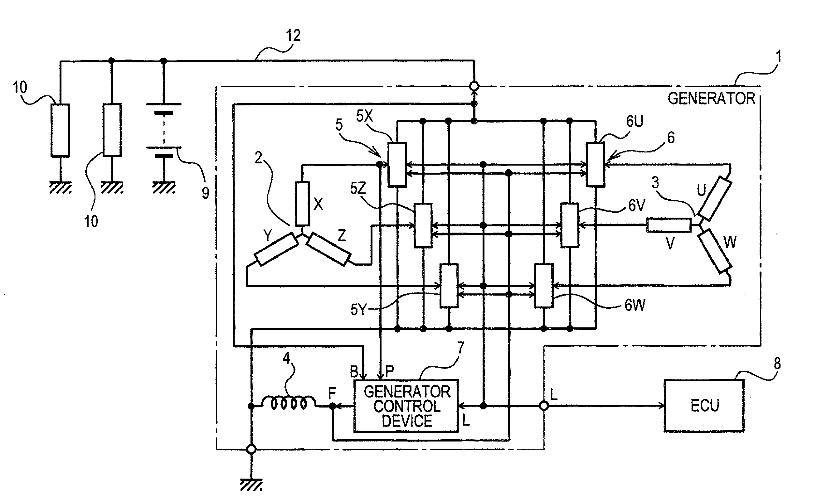
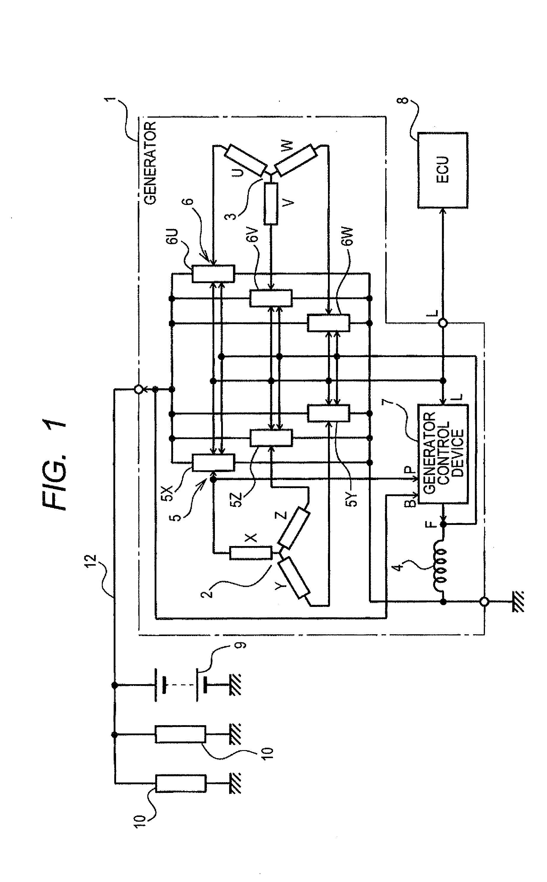
[0142]The generator 1 has a common heat dissipating member to which each of the rectifier modules 5X, 5Y, 5Z, 6U, 6V and 6W is fixedly attached. When overheating has occurred in one of the rectifier modules, heat generated in the overheated rectifier module is quickly transferred to the other rectifier modules through the heat dissipating member. Each of the other rectifier modules receiving the transferred heat starts the overheating protecting operation to decrease the temperature of the rectifier module. Therefore, not only one rectifier module, in which overheating has occurred, starts the overheating protecting operation in response to the occurrence of overheating, but also each of the other rectifier modules starts the overheating protecting operation in response to the heat transferred through the heat dissipating member.
[0143]Accordingly, the difference in start timings of the overheating protecting operations performed in all the rectifier modules can be reduced. That is, ...
second modification
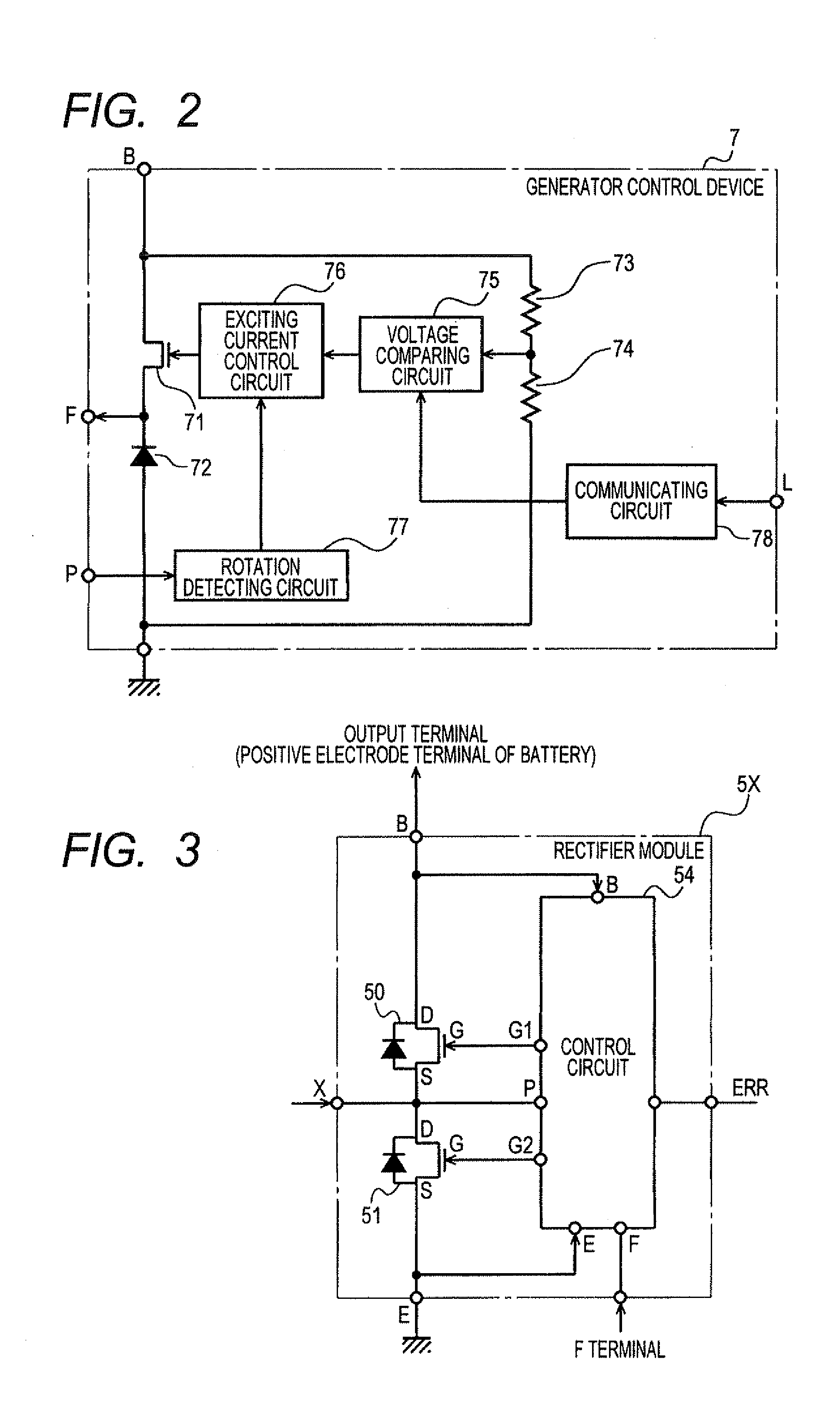
[0149]The overheating protecting blocks 123 of the rectifier modules 5X, 5Y, 5Z, 6U, 6V and 6W are connected with one another through a common connection line. A voltage signal, indicating that at least one of the rectifier modules is now performing the overheating protecting operation, is sent from this module to the other rectifier modules through the connection line.
[0150]FIG. 19 is a block diagram of one rectifier module required to receive and send a voltage signal indicating the occurrence of overheating according to the second modification of this embodiment. As shown in FIG. 19, the generator 1 has a connection line 240, a pull-up resistor 242 through which the connection line 240 is pulled up to the high level, a connection line driving unit 200 arranged in each rectifier module, and a different phase monitoring unit 210 arranged in each rectifier module. The connection line 240 is connected with an error terminal ERR of the driving unit 200 of each rectifier module, and th...
third modification
[0161]The overheating protecting blocks 123 of the rectifier modules 5X, 5Y, 5Z, 6U, 6V and 6W are connected with one another through the signal line, connecting the device 7 and the ECU 8, and information, indicating that one rectifier module is now performing the overheating protecting operation, is sent from this rectifier module to the other rectifier modules through the signal line.
[0162]FIG. 20 is a block diagram of one rectifier module required to receive and send information indicating the occurrence of overheating according to the third modification of this embodiment. As shown in FIG. 20, the generator 1 has a communication line 190, a communication circuit 180 arranged in each rectifier module, an overheating information receiving and sending unit 250 arranged in each rectifier module, and the OR circuit 230 arranged in each rectifier module. The communication circuits 180 of the modules are connected with one another through the communication line 190, and the line 190 i...
PUM
 Abstract
Description
Claims
Application Information
 - R&D Engineer
- R&D Manager
- IP Professional
- Industry Leading Data Capabilities
- Powerful AI technology
- Patent DNA Extraction
Browse by: Latest US Patents, China's latest patents, Technical Efficacy Thesaurus, Application Domain, Technology Topic.
© 2024 PatSnap. All rights reserved.Legal|Privacy policy|Modern Slavery Act Transparency Statement|Sitemap