Display sheet, display device, and electronic apparatus

a display device and electronic equipment technology, applied in the direction of optics, instruments, optical elements, etc., can solve the problems of degrading display characteristics, reducing display surface, degrading effective display area, etc., and achieve excellent display characteristics, high reliability, and high reliability

Active Publication Date: 2012-04-26
E INK CORPORATION
View PDF4 Cites 20 Cited by
  • Summary
  • Abstract
  • Description
  • Claims
  • Application Information

AI Technical Summary

Benefits of technology

[0008]An advantage of some aspects of the invention is to provide a display sheet which has high reliability and can exhibit excellent display characteristics, a display device which is provided therewith, and an electronic apparatus with high reliability.

Problems solved by technology

However, in the “partition type”, there is a problem in that an effective display area (which is an area capable of changing a display color) in a display surface is reduced due to the partitions, and display characteristics are degraded.
In addition, in the “micro capsule type”, there is a problem in that a gap is generated between adjacent micro capsules reducing the effective display area in the display surface, such that the display characteristics are degraded, or when a voltage is applied between the pair of electrodes, leakage current occurs due to the binders, such that the display characteristics are degraded.
However, there is a problem in that, for example, when the display is erected like a book, the white particles and the black particles move (sink) on the lower side in the vertical direction by their own weight and a display image may not be maintained, such that reliability is decreased.

Method used


Image

  • Display sheet, display device, and electronic apparatus
  • Display sheet, display device, and electronic apparatus
  • Display sheet, display device, and electronic apparatus

Examples


first embodiment

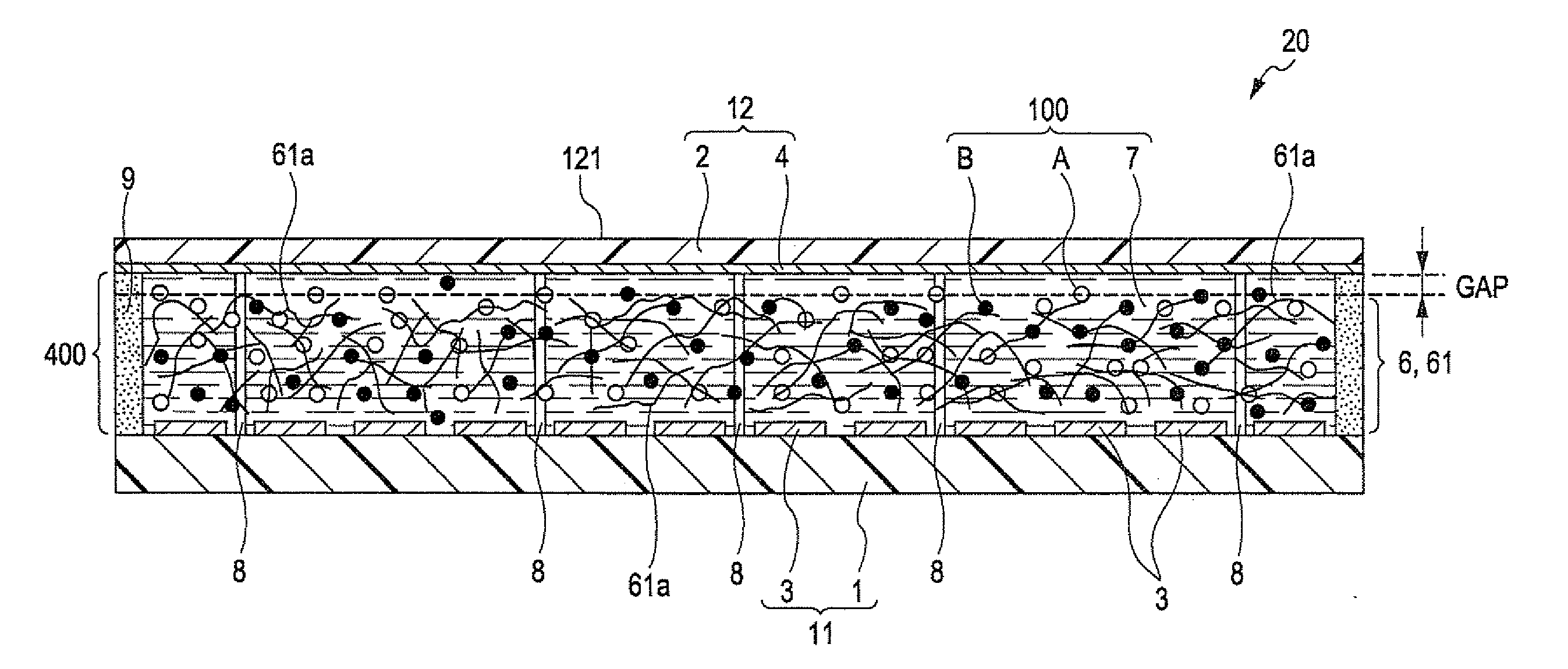
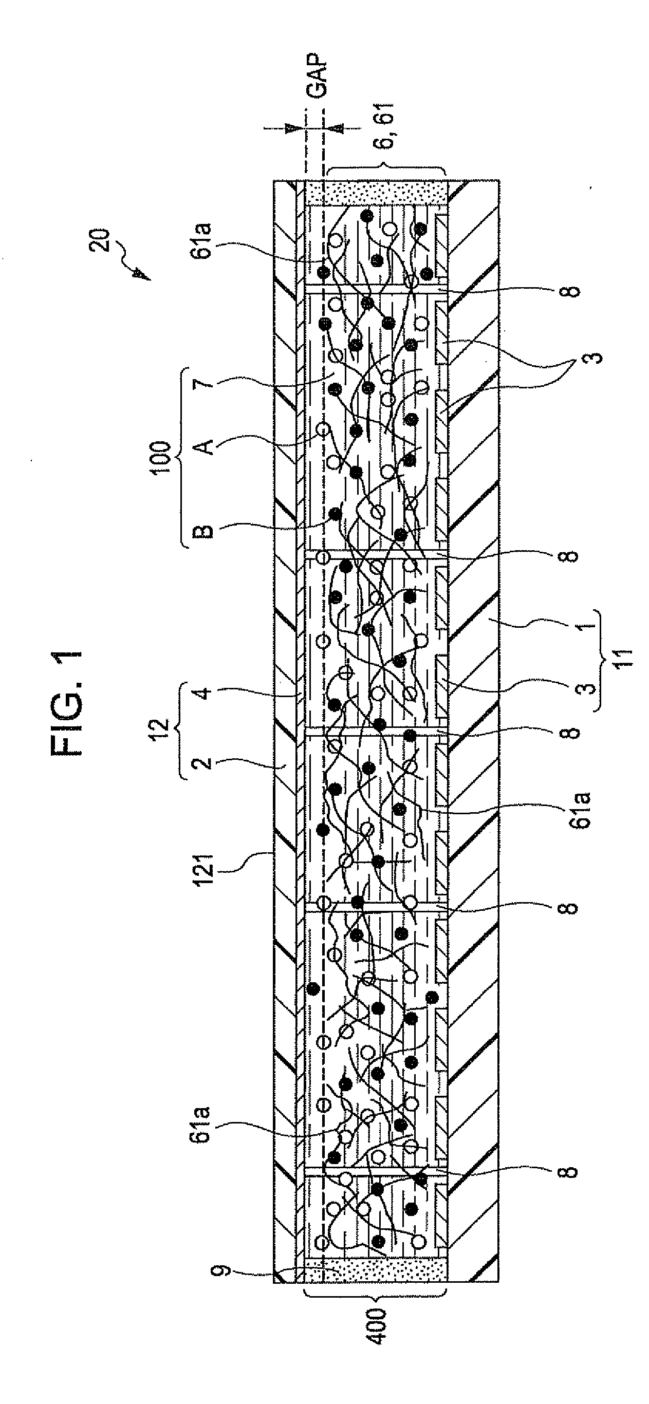
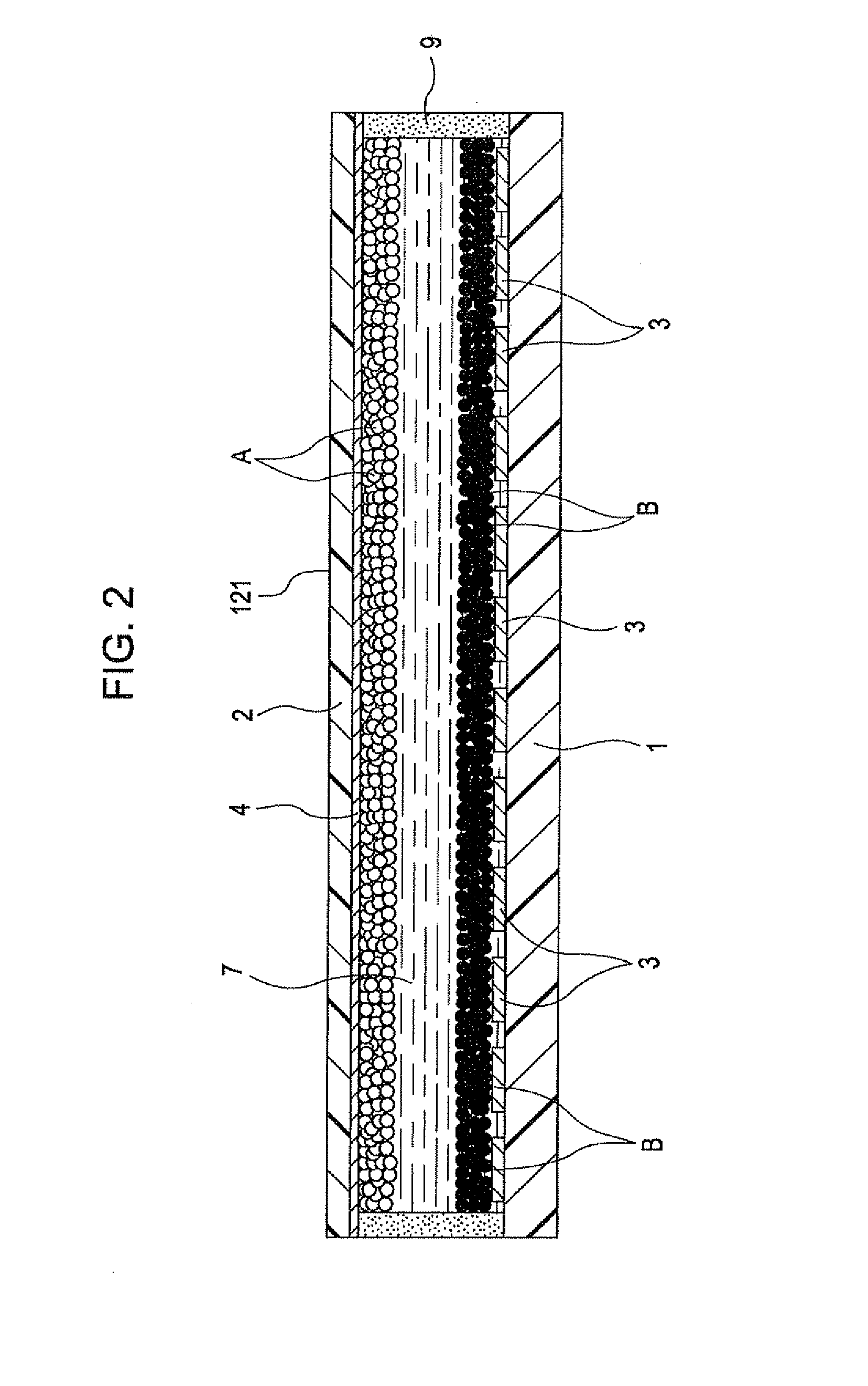
[0047]FIG. 1 is a cross-sectional view illustrating the display device according to the first embodiment of the invention; FIGS. 2 and 3 are diagrams illustrating problems of the display device in the related art; and FIGS. 4A, 4B, 5A, and 5B are cross-sectional views each illustrating driving and effects of the display device shown in FIG. 1. Further, in the following, for convenience of explanation, the upper side and the lower side are denoted by “UPPER” and “LOWER” in FIGS. 1 to 6, respectively.

[0048]The display device (the display device according to the invention) 20 shown in FIG. 1 is an electrophoresis display device which displays desired images using electrophoresis of particles. The display device 20 includes a display sheet (front plane) 21 and a circuit substrate (back plane) 22.

[0049]As shown in FIG. 1, the display sheet 21 includes a substrate (first substrate) 12 which includes a tubular base section 2 and a second electrode 4 provided on the bottom surface of the ba...

second embodiment

[0123]FIG. 6 is a cross-sectional view illustrating the display device according to the second embodiment of the invention.

[0124]Hereinafter, the second embodiment will be described focusing on differences from the above-mentioned embodiment, and the description on the same contents will be omitted.

[0125]The display device according to the second embodiment of the invention is the same as the display device according to the first embodiment except the arrangement of the particle constrained layer. Further, the same components as those in the first embodiment described above are designated by the same reference numerals.

[0126]As shown in FIG. 6, the particle constrained layer 6 according to the embodiment is disposed so as to be separated from the counter substrate 11. It is preferable that a separated distance between the particle constrained layer 6 and the counter substrate 11 is substantially the same as that between the particle constrained layer 6 and the substrate 12, but the ...

third embodiment

[0128]FIG. 7 is a perspective view schematically illustrating the display device according to the third embodiment of the invention, and FIG. 8 is a cross-sectional view illustrating the display device shown in FIG. 7.

[0129]Hereinafter, the third embodiment will be described focusing on differences from the above-mentioned embodiment, and the description on the same contents will be omitted.

[0130]The display device according to the third embodiment of the invention is the same as the display device according to the first embodiment except that the display sheet is configured as a separated body.

[0131]As shown in FIG. 7, a display device 20E according to the embodiment includes a display sheet 21E and a writing device 22E.

[0132]The display sheet 21E, as shown in FIG. 8, includes a substrate (first substrate) 12E, a substrate (second substrate) 11E which is disposed to face the substrate 12E, the display layer 400 which is provided between the substrates 12E and 11E, the particle cons...


PUM

PropertyMeasurementUnit
widthaaaaaaaaaa
widthaaaaaaaaaa
widthaaaaaaaaaa

Abstract

A display device includes: a substrate provided on a side of the display surface; a counter substrate disposed to face the substrate; a display layer provided between the substrate and the counter substrate and filled with a dispersion liquid formed of a dispersion medium in which white particles and black particles charged with polarities opposite to each other are dispersed; and a particle constrained layer provided in the display layer, and suppresses the white particles and the black particles from moving in an in-plane direction of the display layer, while allowing the particles to move in the thickness direction of the display layer. In the display device, a particle constrained layer is provided to be separated from the substrate.

Description

BACKGROUND[0001]1. Technical Field[0002]The present invention relates to a display sheet, a display device, and an electronic apparatus.[0003]2. Related Art[0004]For example, as a configuration of an image display section of an electronic paper, an electrophoresis display which uses an electrophoresis migration of particles is known (for example, refer to JP-A-2010-44114). The electrophoresis display is excellent in portability and conservation of electric power, and is particularly applied as an image display section of electronic paper.[0005]The electrophoresis display includes a pair of electrodes which are disposed to face each other and a display layer which is provided therebetween. The display layer is filled with, for example, a dispersion liquid which is composed of a liquid phase dispersion medium in which positively charged white particles and negatively charged black particles are dispersed. The electrophoresis display is configured such that a voltage is applied between...

Claims


Application Information

Patent Timeline
Patent Type & Authority Applications(United States)
IPC IPC(8): G02F1/167
CPCG02F1/167G02F1/172G02B26/026G02F2001/1678
Inventor OGAWA, SATOSHI
Owner E INK CORPORATION
Why Eureka
Try Eureka