Supercharge Your Innovation With Domain-Expert AI Agents!

Radio communication system, radio base station, and radio communication method

a radio communication system and radio communication technology, applied in the field of radio communication systems, radio base stations, radio communication methods, can solve the problems of wasteful consumption of radio resources used in coordinated communications by the first radio base stations, low frequency usage efficiency of normal mimo communications, etc., to achieve the effect of reducing interference, reducing transmission power to the radio terminal ue2, and improving channel quality

Inactive Publication Date: 2012-04-26
KYOCERA CORP
View PDF9 Cites 9 Cited by
  • Summary
  • Abstract
  • Description
  • Claims
  • Application Information

AI Technical Summary

Benefits of technology

The present invention provides a radio communication system, method, and base station that effectively utilize a radio resource used in coordinated communications, also known as CoMP, by allocating the resource to a different radio terminal if a predetermined condition is met. This helps to avoid wasting the radio resource and ensures efficient communication performance. Additionally, the invention takes into account the channel quality between the radio terminal and the base station to optimize the use of the radio resource.

Problems solved by technology

The coordinated communications (CoMP) can improve the communication performance as compared with normal MIMO communications, but achieves lower frequency usage efficiency than the normal MIMO communications because the radio resource is consumed by both of the first radio base station and the second radio base station.
Furthermore, the coordinated communications of the JP scheme have the following problem.
In such case, there is a problem that the radio resource used in coordinated communications by the first radio base station is wastefully consumed because a sufficient throughput can be obtained with the second radio base station alone.

Method used


Image

  • Radio communication system, radio base station, and radio communication method
  • Radio communication system, radio base station, and radio communication method
  • Radio communication system, radio base station, and radio communication method

Examples


first embodiment

[0033]Hereinafter, a description will be given of a radio communication system according to the first embodiment of the present invention with reference to the drawings. To put it more specifically, a description will be given of (1) Configuration of Radio Communication System, (2) Configuration of Radio Base Station, (3) Operation of Radio Communication System, and (4) Effects of First Embodiment.

(1) Configuration of Radio Communication System

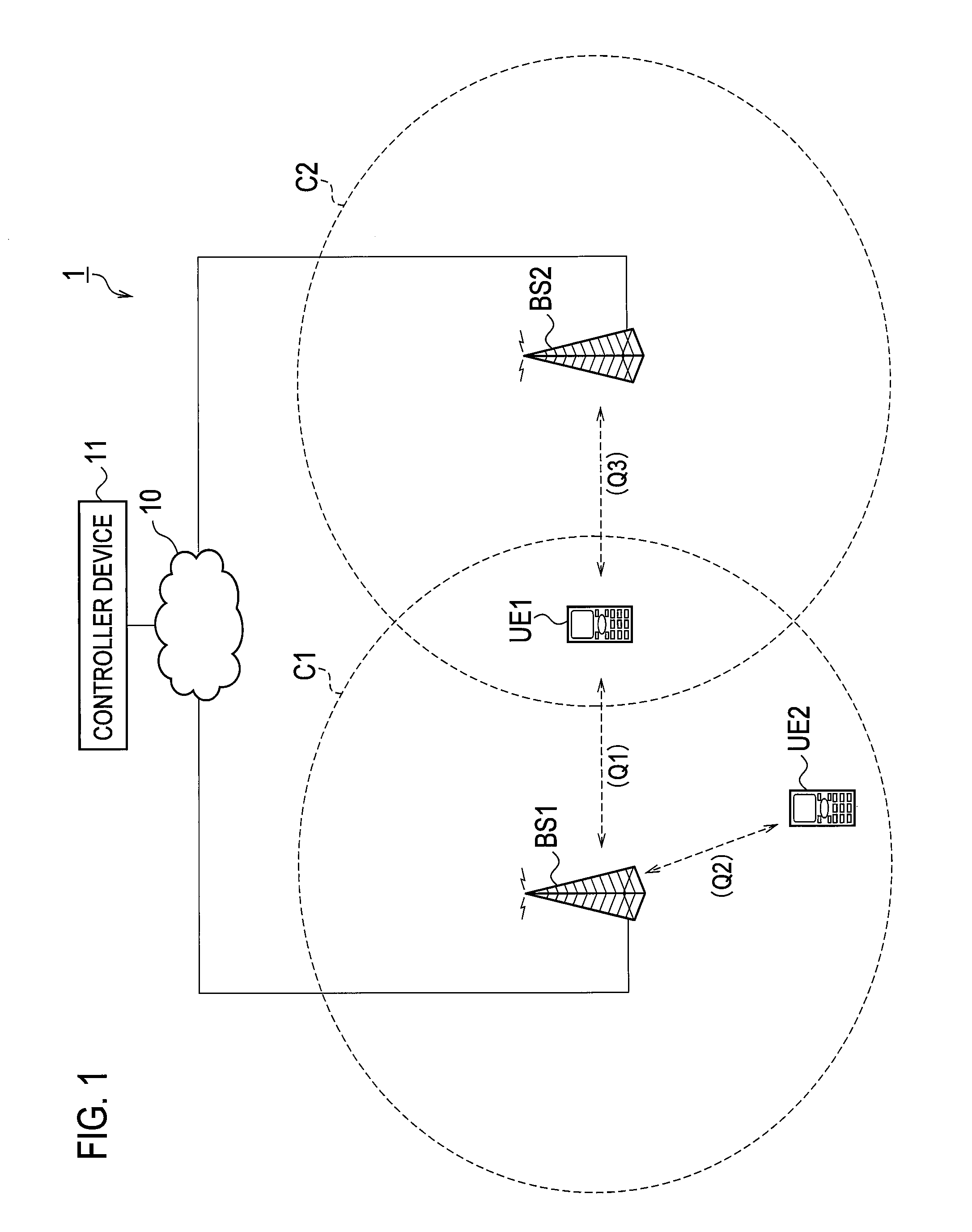
[0034]FIG. 1 is a schematic configuration diagram of a radio communication system 1 according to the first embodiment. The radio communication system 1 has a configuration based on LTE-Advanced, which is considered as the fourth generation (4G) cellular phone system, and supports CoMP (Coordinated Communications).

[0035]As shown in FIG. 1, the radio communication system 1 includes a radio base station BS1 (first radio base station), a radio base station BS2 (second radio base station), a radio terminal UE1 (first radio terminal), a radio termin...

example 1

(3.2.1) Operation Sequence Example 1

[0062]FIG. 4 is a sequence diagram showing an operation sequence example 1 of the radio communication system 1.

[0063]In step S100, the controller device 11, the radio base station BS1, the radio base station BS2 and the radio terminal UE1 perform a setting procedure for starting CoMP.

[0064]In step S101, the radio base station BS1 and the radio base station BS2 perform CoMP with the radio terminal UE1 by using the radio resource R1.

[0065]In step S102, the radio terminal UE2 transmits a pilot signal 2. In step S103, the radio terminal UE1 transmits a pilot signal 1. Note that, each pilot signal is periodically transmitted thereafter.

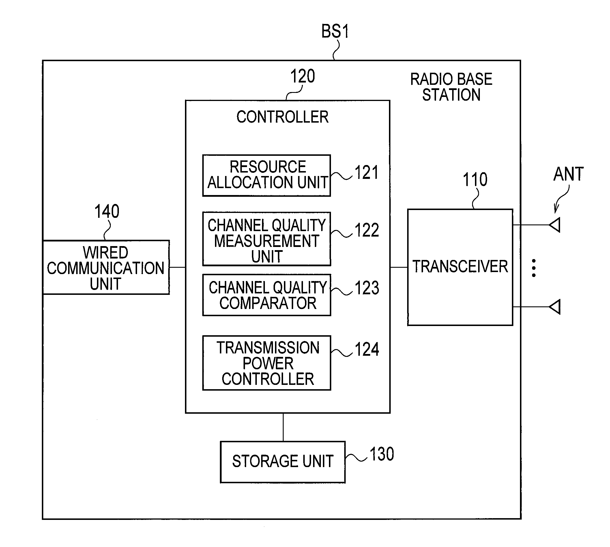
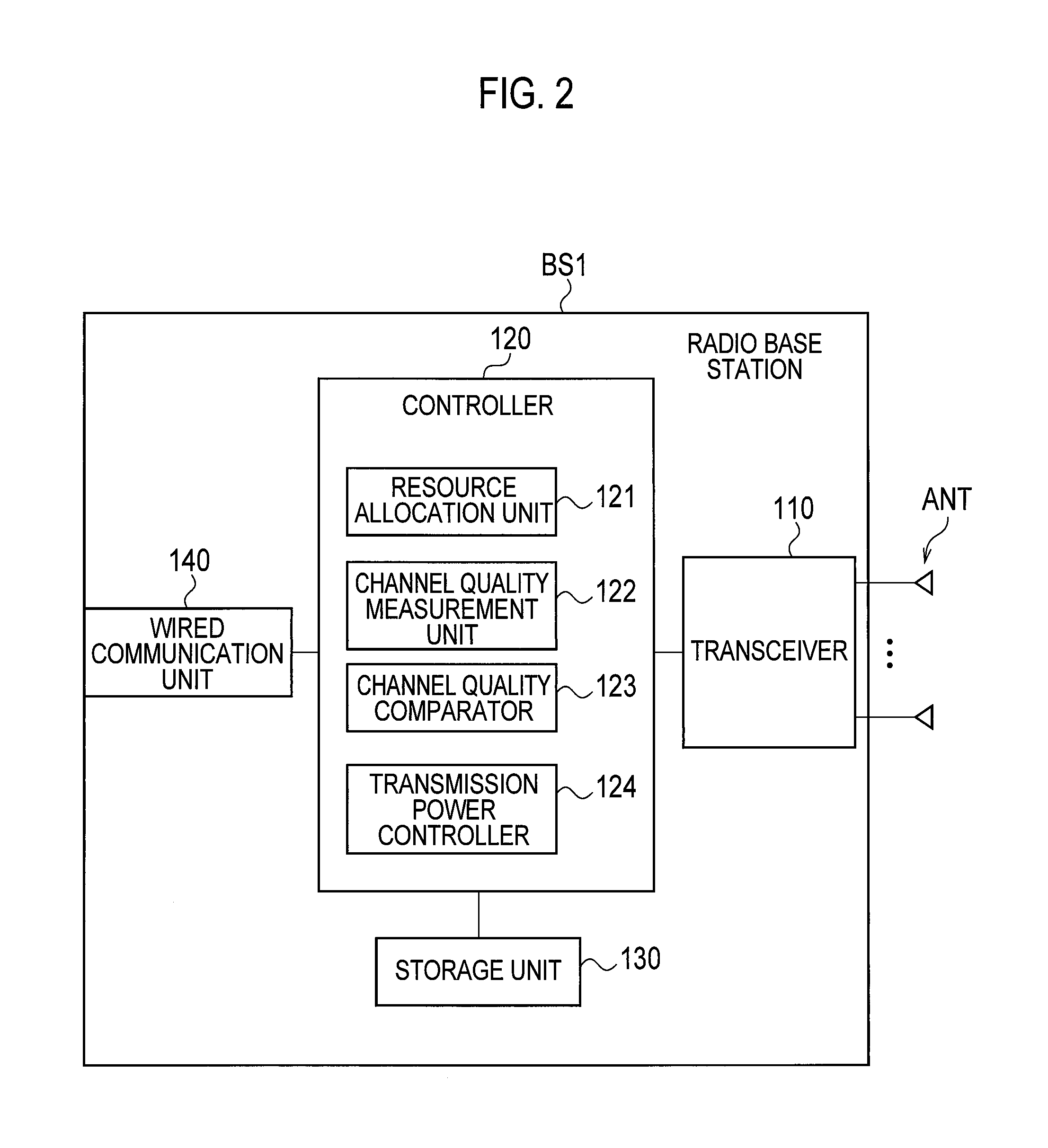
[0066]In step S104, the channel quality measurement unit 122 of the radio base station BS1 measures the channel quality Q1 from the pilot signal 1 received from the radio terminal UE1 and also measures the channel quality Q2 from the pilot signal 2 received from the radio terminal UE2.

[0067]In step S105, the radio base s...

example 2

(3.2.2) Operation Sequence Example 2

[0082]FIG. 5 is a sequence diagram showing an operation sequence example 2 of the radio communication system 1. While the controller device 11 performs the comparison between the predetermined quality and the channel quality Q3 in the operation sequence example 1 described above, the radio base station BS1 performs this comparison in this operation example.

[0083]The processing in steps S200 to S205 is executed in the same manner as in the case of steps S100 to S105 in the operation sequence example 1 described above.

[0084]In step S206, the radio base station BS2 transmits the channel quality Q3 measured in step S205 (or an index of the channel quality Q3) to the radio base station BS1 through the communications between the base stations.

[0085]In step S207, the channel quality comparator 123 of the radio base station BS1 compares the channel quality Q1 and the channel quality Q2, which are measured in step S204. In this operation example, an assump...


PUM


Abstract

A radio communication system (1) wherein a radio base station (BS1), which allocates to a radio terminal (UE1) a radio resource specified by the combination of a frequency and a time, and a radio base station (BS2), which allocates to the radio terminal (UE1) the same radio resource, use this radio resource to perform a cooperative communication with the radio terminal (UE1). In the radio communication system (1), if a predetermined condition, which indicates that the status of the communication between the radio base station (BS2) and the radio terminal (UE1) is good, is satisfied and further if a propagation path quality (Q2) between the radio base station (BS1) and a radio terminal (UE2) is better than a propagation path quality (Q1) between the radio base station (BS1) and the radio terminal (UE1), then the radio base station (BS1) allocates the foregoing radio resource to the radio terminal (UE2) instead of the radio terminal (UE1).

Description

TECHNICAL FIELD[0001]The present invention relates to a radio communication system in which multiple radio base stations communicate with a single radio terminal while using the same radio resource, and also relates to a radio base station and a radio communication method.BACKGROUND ART[0002]One of known conventional techniques capable of improving the frequency usage efficiency in a radio communication system is MIMO (Multi-Input Multi-Output) communications in which a transmission side transmits and a reception side receives radio signals by using the same radio resource (combination of frequency and time) while each using multiple antennas.[0003]In recent years, coordinated MIMO communications (hereinafter, referred to as “coordinated communications” as needed) have been attracting attention as an advanced technique of MIMO communications. In the coordinated communications, multiple radio base stations make use of communications between the base stations to communicate with a sin...

Claims


Application Information

Patent Timeline
Patent Type & Authority Applications(United States)
IPC IPC(8): H04W4/06
CPCH04B7/022H04W72/044H04W52/40
Inventor YAMAZAKI, CHIHARU
Owner KYOCERA CORP
Features
  • R&D
  • Intellectual Property
  • Life Sciences
  • Materials
  • Tech Scout
  • Unparalleled Data Quality
  • Higher Quality Content
  • 60% Fewer Hallucinations
Learn More