
Optical communication card and optical transmission device

a communication card and optical transmission technology, applied in the field of optical communication cards and optical transmission devices, can solve the problems of increasing power consumption, affecting the operation of the device, so as to reduce the power consumption of the fec function. effect of the devi

Inactive Publication Date: 2012-04-26
HITACHI LTD
View PDF35 Cites 4 Cited by
  • Summary
  • Abstract
  • Description
  • Claims
  • Application Information

AI Technical Summary

Benefits of technology

The invention is about reducing power consumption in an optical transmission device with a large capacity while maintaining transmission quality. The device uses a FEC function for error correction, but this function increases power consumption and bit error occurrence. The invention proposes a method for controlling the FEC function based on the transmission speed and bit error rate of each transmission line in the device. This allows for the selection of the most suitable FEC function for each line, reducing power consumption and bit error occurrence. The invention also includes a data table that associates each transmission line with multiple FEC functions to further optimize the selection process. Overall, the invention achieves reliable communication with low power consumption.

Problems solved by technology

On the other hand, as to the large capacity, increasing signal processing operation because of adding the FEC function further increases power consumption, in addition to increasing signal processing operation because of a high-speed signal.
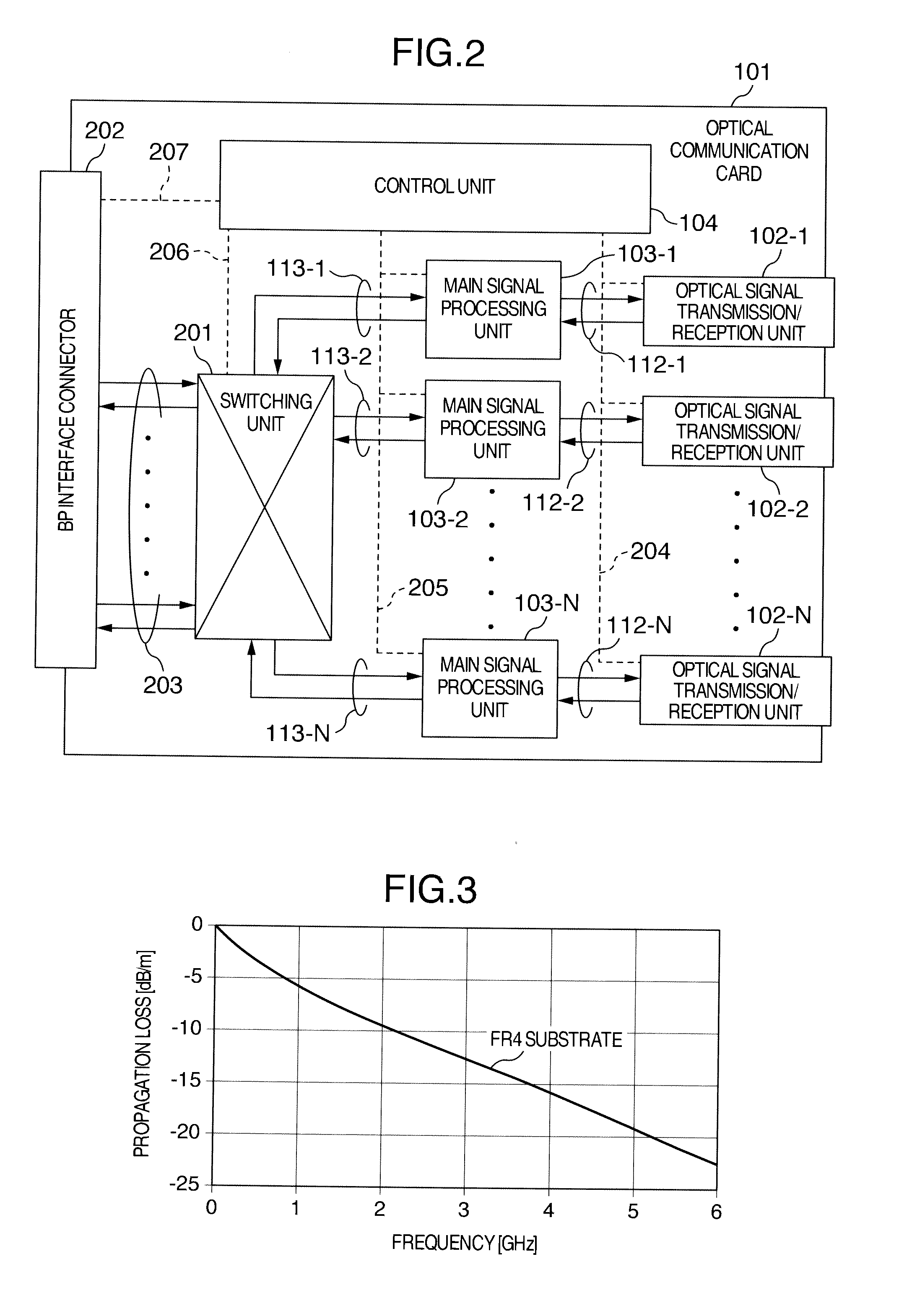
However, the propagation loss is practically different depending on the transmission speed or each transmission line in the device.
Therefore, for example, in a transmission line which is low speed or has small attenuation, the FEC function may be unnecessary.
By using the FEC function also for such a transmission line which needs little FEC function, power consumption increases more than necessary.
However, since the number of bit errors of the main signal during practical operation is monitored on the decoder side, the FEC function cannot be validated before a bit error occurs.
In short, there arises a problem of the maintenance of reliability as the optical transmission device.

Method used


Image

  • Optical communication card and optical transmission device
  • Optical communication card and optical transmission device
  • Optical communication card and optical transmission device

Examples


Embodiment Construction

[0029]An optical transmission system using the present invention will be described below. Note that the present invention should not be limited by the embodiment described below.

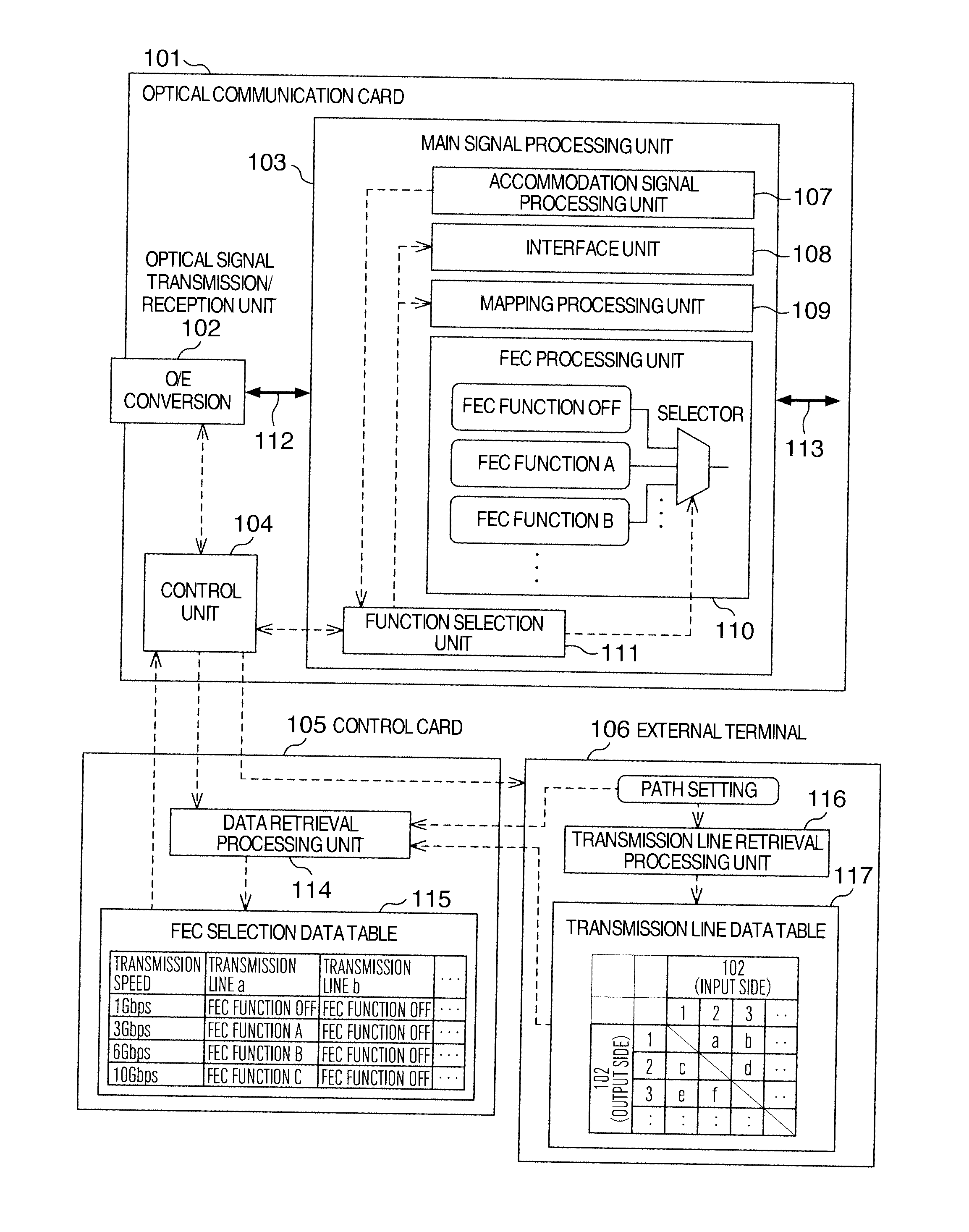
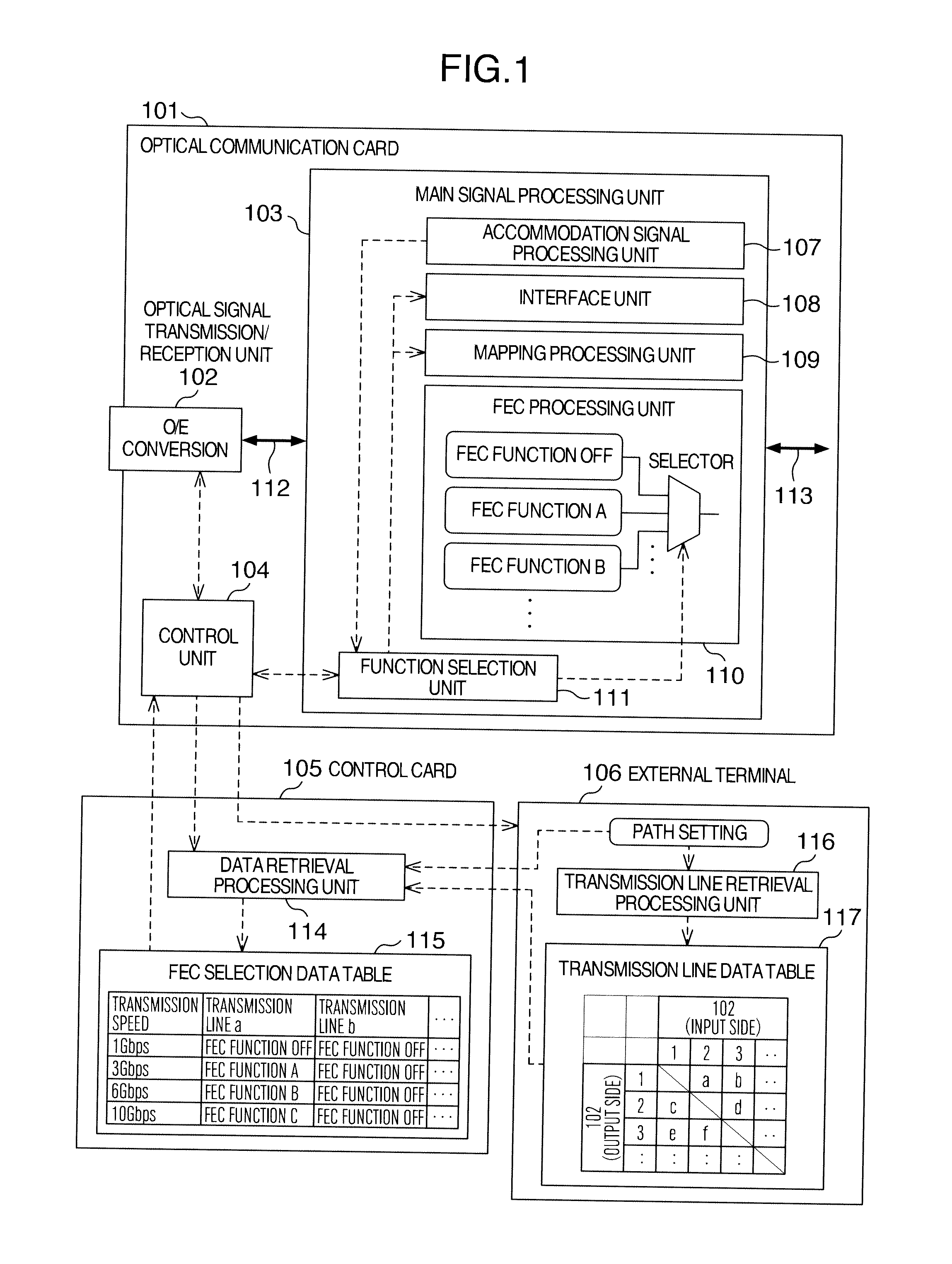
[0030]FIG. 1 illustrates a configuration of the optical communication card, control card and external terminal according to the present embodiment focusing on a configuration of a main signal processing unit of the optical communication card. Here, the optical transmission device is mounted with one or more optical communication cards and the control card capable of controlling the cards in the device.

[0031]The optical communication card 101 in FIG. 1 comprises a main signal processing unit 103 including a selection function about multiple types of FEC functions. The optical communication card 101 illustrated in FIG. 1 transmits / receives a main signal transmitted over a network outside the device. The optical communication card 101 comprises multiple optical signal transmission / reception units 102 that perfo...


PUM


Abstract

There arises a problem that power consumption increases along with an increasing throughout of an FEC function effective in speeding up of a transmission speed. FEC function information necessary for a system is prepared, and multiple FEC functions are properly used according to a selected transmission line, etc.

Description

INCORPORATION BY REFERENCE[0001]The present application claims priority from Japanese application JP2010-236977 filed on Oct. 22, 2010, the content of which is hereby incorporated by reference into this application.BACKGROUND OF THE INVENTION[0002]The present invention relates to an optical communication card comprising a forward error correction (FEC) function and to an optical transmission device[0003]Along with the recent popularization of an optical communication technology in various fields such as the Internet (registered trademark) and optical phones, various technologies to realize a long distance transmission and a large-capacity transmission have been developed in an optical transmission system.[0004]As to the long distance transmission, in general, as a propagation distance becomes longer, a data error in a signal propagation due to an influence of a propagation loss in an optical fiber becomes more prominent. Therefore, an error correction function called an FEC function...

Claims


Application Information

Patent Timeline
Patent Type & Authority Applications(United States)
IPC IPC(8): H04B10/00H04B10/04H04L1/00
CPCH04B10/516H04B10/40
Inventor KAMAKURA, MASAFUMITAKATORI, KOJIFUKASHIRO, YASUYUKIUDA, TETSUYANARITA, HIDEMASA
Owner HITACHI LTD
Learn More