Sound effect generating device

a sound effect and generating device technology, applied in the field of sound effect generating devices, can solve the problems of aging of individual units of sound, performance variations and other problems of the above-mentioned publication

Active Publication Date: 2012-04-26
HONDA MOTOR CO LTD
View PDF1 Cites 20 Cited by
  • Summary
  • Abstract
  • Description
  • Claims
  • Application Information

AI Technical Summary

Benefits of technology

[0007]The present invention has been made in view of the above problems. It is an object of the present invention to provide a sound effect generating device, which is capable of compensating for performance variations and aging of a sound effect output means.
[0009]According to the present invention, the gain for the control signal, which represents the sound effect, is corrected based on the result of the comparison between the predicted gain for the sound effect based on the traveling state of the mobile body (e.g., at least one of an engine rotational frequency, an engine rotational frequency change, a rotational frequency of a traction motor, a rotational frequency change of a traction motor, a vehicle speed, and a vehicle speed change). Therefore, even if the measured gain of the sound effect varies due to aging of the sound effect output means, the output level of the sound effect output means is kept constant when the vehicle is in a prescribed traveling state, and hence aging of the sound effect output means can be compensated for. If the predicted gain is shared by a plurality of sound effect generating devices, then it is also possible to compensate for performance variations of the sound effect generating devices.
[0010]The gain comparing means may comprise predicted gain identifying means for identifying a predicted gain of the certain order based on the second gain table, and measured gain detecting means for detecting a measured gain of the certain order from the sound effect at the evaluating position. It is thus possible to identify the predicted gain and the measured gain based on only the certain order, and thus the predicted gain and the measured gain can be identified with higher accuracy than if the order were not identified.
[0012]The gain comparing means may compare the predicted gain and the measured gain with each other at a frequency for setting the gain for the control signal to a relatively large value with the acoustic control means, from among control frequencies for the control signal. Alternatively, the gain correcting means may correct the gain for the control signal at a frequency for setting the gain for the control signal to a relatively large value with the acoustic control means.
[0014]According to the present invention, the gain for the control signal, which represents the sound effect, is corrected based on the result of the comparison between the gain for the control signal and the measured gain of the sound effect. Therefore, even if the measured gain of the sound effect varies due to aging of the sound effect output means, the output level of the sound effect output means is kept constant when the vehicle is in a prescribed traveling state, and hence aging of the sound effect output means can be compensated for. If the gain for the control signal and the signal transfer characteristic are shared by a plurality of sound effect generating devices, then it also is possible to compensate for performance variations of the sound effect generating devices.
[0016]According to the present invention, the gain for the control signal, which represents the sound effect, is corrected based on the result of the comparison between the reference sound volume level for the sound effect and the measured sound volume level of the sound effect. Therefore, even if the measured gain of the sound effect varies due to aging of the sound effect output means, the output level of the sound effect output means is kept constant when the vehicle is in a prescribed traveling state, and hence aging of the sound effect output means can be compensated for. If the reference sound volume level is shared by a plurality of sound effect generating devices, then it also is possible to compensate for performance variations of the sound effect generating devices.

Problems solved by technology

For example, the above publications do not take into account performance variations and aging of individual units of the sound effect output means (e.g., speakers).

Method used


Image

  • Sound effect generating device
  • Sound effect generating device
  • Sound effect generating device

Examples


embodiment

A. Embodiment

1. Overall and Partial Configurations

(1) Overall Configuration

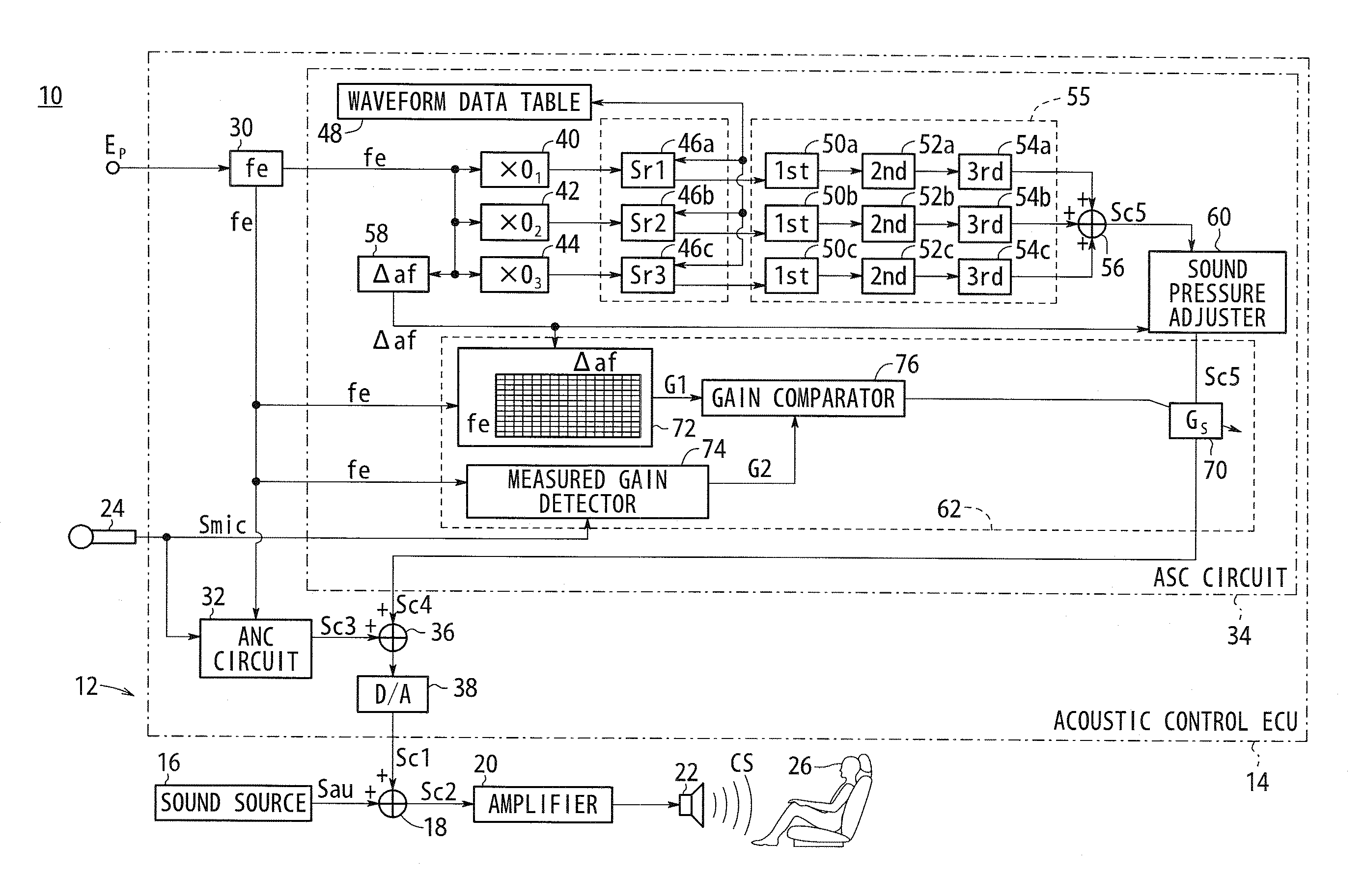
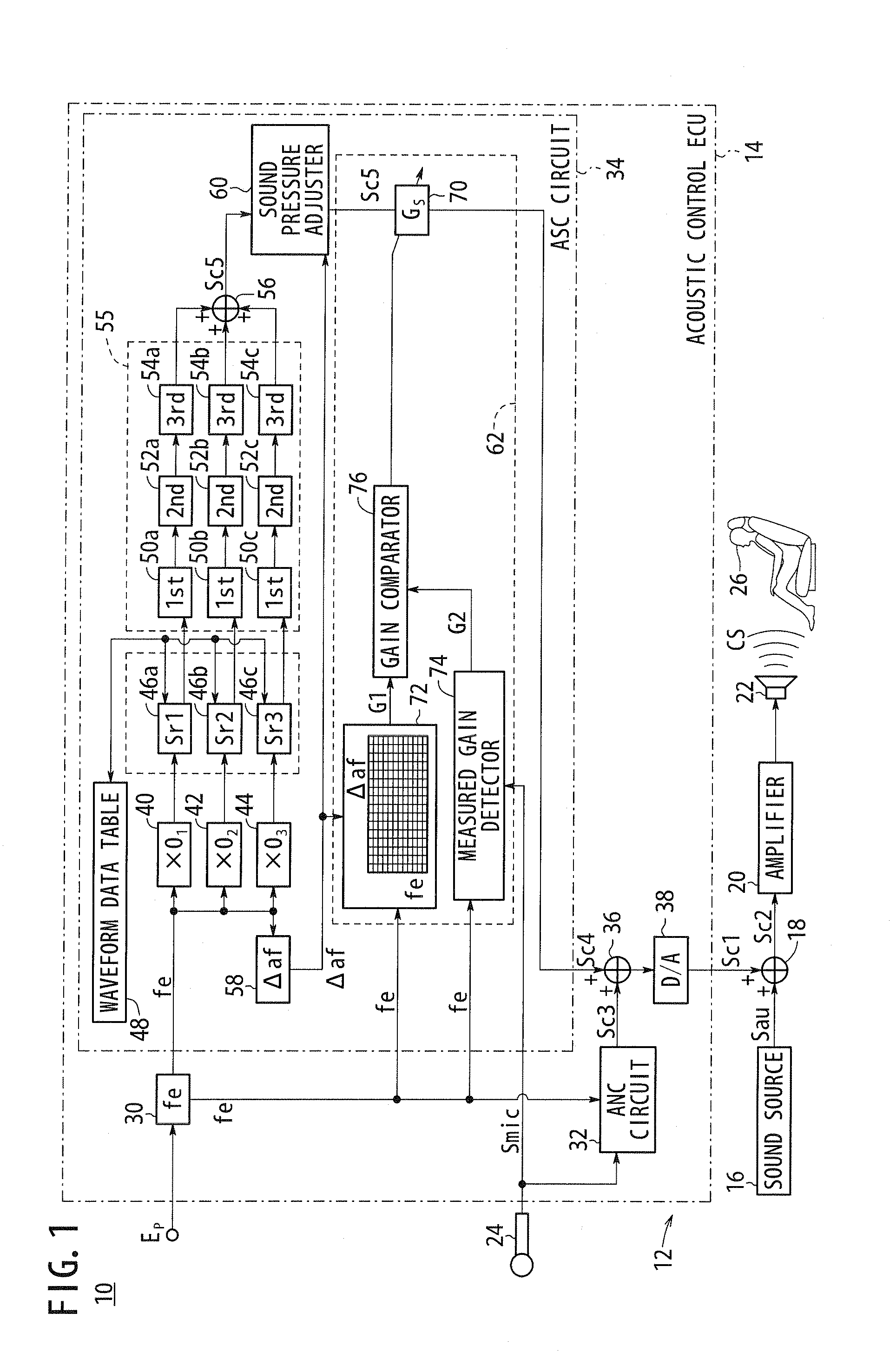
[0022]FIG. 1 is a schematic diagram of a vehicle 10 incorporating an acoustic control ECU 14 (ECU: Electronic Control Unit), which functions as a sound effect generating device (ASC device) according to an embodiment of the present invention. The vehicle 10 is a gasoline-powered vehicle, although the vehicle 10 may be another vehicle such as an electric vehicle, a fuel cell vehicle, or the like.

[0023]The vehicle 10 has an acoustic system 12 including, in addition to the acoustic control ECU 14, a sound source 16, an adder 18, an amplifier 20, a speaker 22, and a microphone 24.

[0024]The acoustic control ECU 14 (hereinafter referred to as an “ECU 14”) functions both as an active noise control device (hereinafter referred to as an “ANC device”) and as an ASC device. When the ECU 14 functions as an ANC device, a control signal Sc1 output from the ECU 14 represents a cancellation sound for canceling noise (muffled...


PUM


Abstract

A control signal generating means of a sound effect generating device sets the reference volume that is the reference value of the volume of a sound effect when a vehicle is in a predetermined travel state, compares the measured volume of the sound effect detected by a sound effect detecting means when the vehicle is in the predetermined travel state and the reference volume, and corrects the gain of a control signal on the basis of the result of the comparison.

Description

TECHNICAL FIELD[0001]The present invention relates to a sound effect generating device for generating a sound effect such as a vehicular pseudo-engine sound or the like.BACKGROUND ART[0002]Sound effect generating devices, which serve as equipment for enhancing an acoustic effect in vehicle passenger compartments (hereinafter referred to as ASC (ASC: Active Sound Control) devices) are known (see, for example, U.S. Patent Application Publication No. 2006 / 0215846, U.S. Pat. No. 5,635,903, and Japanese Laid-Open Patent Publication No. 2006-193002).[0003]According to U.S. Patent Application Publication No. 2006 / 0215846, a plurality of reference signals (Sr1, Sr2, Sr3) depending on engine rotational frequency [Hz] are generated. After a predetermined gain correcting process is performed on the reference signals, the reference signals are combined into a control signal (Sc) for generating a sound effect. Then, a gain correcting process depending on a change [Hz / s] in the engine rotational ...

Claims


Application Information

Patent Timeline
Patent Type & Authority Applications(United States)
IPC IPC(8): G06F17/00
CPCG10K15/02G10K2210/3213G10K2210/1282
Inventor INOUE, TOSHIOKOBAYASHI, YASUNORI
Owner HONDA MOTOR CO LTD
Why Eureka
Try Eureka