Distributed flight control system implemented according to an integrated modular avionics architecture

a flight control system and modular technology, applied in the field of flight control systems, can solve the problems of reducing the auto-pilot function of the airplane, increasing the exposure to electromagnetic disturbance risks, and restricting the aircraft's weight budget,

Active Publication Date: 2012-04-26
AIRBUS OPERATIONS (SAS)
View PDF61 Cites 44 Cited by
  • Summary
  • Abstract
  • Description
  • Claims
  • Application Information

AI Technical Summary

Problems solved by technology

This flight control system has a certain number of drawbacks, including the need to deploy a large number of cables between the computers on the one hand and the actuators and control surfaces they control on the other.
This cable deployment strains the aircraft's weight budget and increases the exposure to risks of electromagnetic disturbances.
Moreover, the secondary computers do not make it possible to perform the auto-pilot function of the airplane, unlike the primary systems.

Method used


Image

  • Distributed flight control system implemented according to an integrated modular avionics architecture
  • Distributed flight control system implemented according to an integrated modular avionics architecture
  • Distributed flight control system implemented according to an integrated modular avionics architecture

Examples


first embodiment

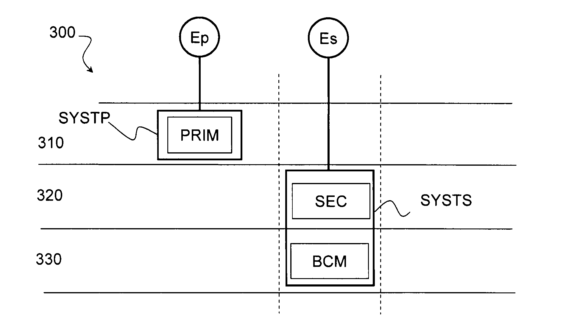
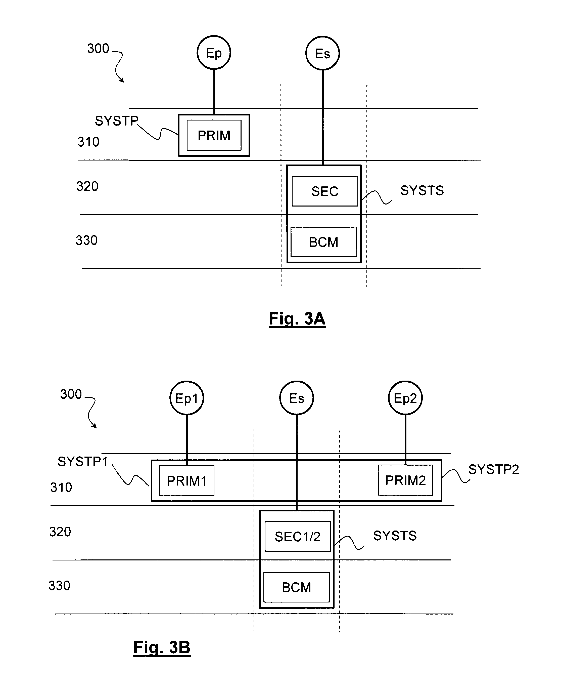
[0044]FIG. 3A diagrammatically illustrates a flight control system according to the invention.

[0045]The flight control system 300 comprises two independent control systems respectively designated by SYSTP and SYSTS. The primary control system, SYSTP, comprises at least one primary computer denoted PRIM, a first set (not shown) of control surface actuators controlled by said computer and a first set (not shown) of sensors monitoring the status of said actuators and associated control surfaces. The primary computer is connected to the first set of actuators and to the first set of sensors by a network, called primary network.

[0046]Similarly, the secondary system SYSTS comprises at least one secondary computer, denoted SEC, a second set of control surface actuators commanded by said computer, and a second set of sensors monitoring the status of said actuators and associated control surfaces. Optionally, the secondary system also comprises a back-up computer BCM, sharing the second set ...

second embodiment

[0049]FIG. 3B diagrammatically shows a flight control system according to the invention.

[0050]Unlike the first embodiment, the primary control system here comprises a plurality of primary computers connected to independent energy sources of different types. The primary computers are generic and have identical structures. This embodiment is preferred when the failure rate of a primary computer is above the level required by the certification body. It will be understood that if the maximum acceptable failure rate level is λ and the average failure rate of a primary computer, considered alone, is λ0, the number n of primary computers will be chosen such that λ0n<λ.

[0051]For illustration purposes, a configuration with two primary computers PRIM1 and PRIM2 has been shown here, but of course the invention applies in general to any number of such computers.

[0052]The computer PRIM1 is, as will be seen in detail later, connected to a first subset of the first set of actuators and a first sub...


PUM


Abstract

A flight control system for an aircraft, intended for controlling a plurality of actuators adapted for actuating control surfaces of the aircraft from information supplied by piloting members and / or sensors of the aircraft. The system includes a primary control system adapted for controlling a first set of control surface actuators and a secondary control system adapted for controlling a second set of control surface actuators, the primary and secondary systems being respectively powered by independent energy sources of different types.

Description

TECHNICAL FIELD[0001]The present invention generally relates to flight control systems in the aeronautics field.BACKGROUND OF THE INVENTION[0002]The flight control system of an aircraft connects the piloting members (control column, rudder bar, etc.) and the aerodynamic tip-control surfaces. Modern jetliners have electric flight control systems in which the mechanical actions on the piloting members are converted into analog signals that are sent to actuators maneuvering the control surfaces.[0003]FIG. 1 illustrates a centralized flight control system 100, known from the state of the art. We have shown a piloting member 110, for example a side-stick controller, equipped with one or more sensors 115, for example position sensors and / or angular sensors providing position and / or orientation information to the flight control computer 120. The computer 120 determines, from information received from the various piloting members 110, including the auto-pilot (not shown) and / or, if applicab...

Claims


Application Information

Patent Timeline
Patent Type & Authority Applications(United States)
IPC IPC(8): G05D1/00B64C13/02
CPCB64C13/42G05B9/03B64C13/503B64C13/505
Inventor FERVEL, MARCLECANU, ARNAUDMAUSSION, ANTOINEAUBERT, JEAN-JACQUES
Owner AIRBUS OPERATIONS (SAS)
Why Eureka
Try Eureka