Portable Linear Generator

a generator and linear technology, applied in the direction of electrical apparatus, dynamo-electric machines, etc., can solve the problems of significant internal friction of devices, significant effort for consumers to charge flashlights, and little commercial use of diamagnetic properties, etc., to reduce internal friction, low cost, and quiet kinetic charging

Inactive Publication Date: 2012-05-03
GENNEO
View PDF11 Cites 36 Cited by
  • Summary
  • Abstract
  • Description
  • Claims
  • Application Information

AI Technical Summary

Benefits of technology

[0011]Another object of the invention is to provide a more efficient kinetic charging device with reduced internal friction and multiple charging pulses from a single mechanical impulse.
[0012]Another object of the invention is to provide a more quiet kinetic charging device.
[0013]A further object of the invention is to provide a low cost and easily manufactured kinetic charging device.

Problems solved by technology

It has thus far seen little commercial use for its diamagnetic property due to how small the diamagnetic forces are compared to the force of gravity acting on the mass of permanent magnets or on the mass of objects to which the pyrolytic graphite might be attached.
While novel and useful for many purposes, these flashlights require significant effort for consumers to charge by shaking or impacting them.
These devices have significant internal friction, and they tend to be noisy when shaken.
Other kinetic charging inventions such as piezoelectric element arrays and mechanical pendulum machines are also available, but these have limited application due to size and efficiency limitations and other concerns.

Method used


Image

  • Portable Linear Generator
  • Portable Linear Generator
  • Portable Linear Generator

Examples


Embodiment Construction

[0022]Detailed descriptions of the preferred embodiment are provided herein. It is to be understood, however, that the present invention may be embodied in various forms. Therefore, specific details disclosed herein are not to be interpreted as limiting, but rather as a basis for the claims and as a representative basis for teaching one skilled in the art to employ the present invention in virtually any appropriately detailed system, structure or manner.

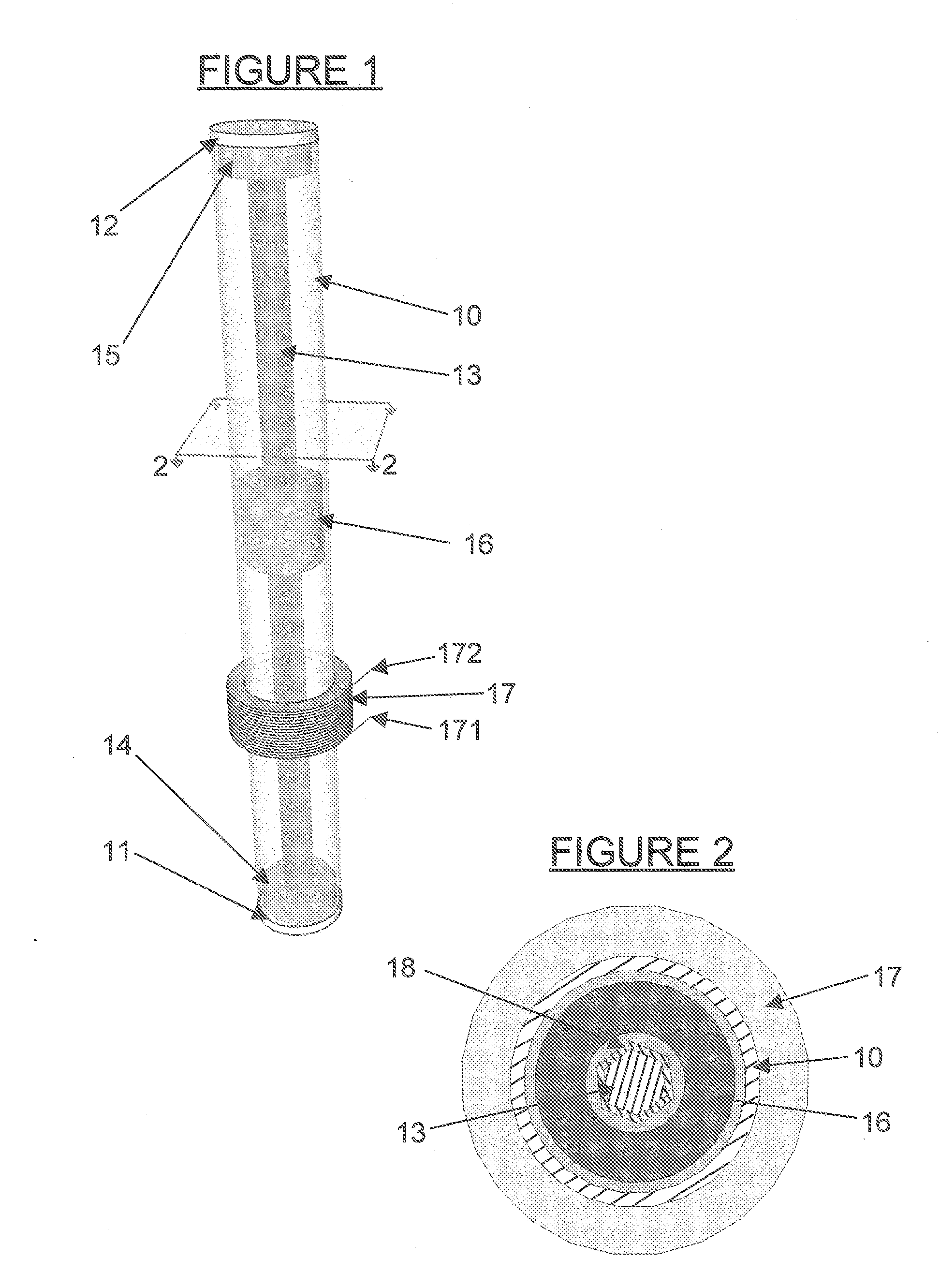
[0023]The preferred configuration and orientation of the portable linear generator will be selected based on the parameters of the portable powered device into which it will be assembled, including the battery capacity and typical discharge rate, the size of the device, and the most common physical orientations for the device when resting, in use, and being carried.

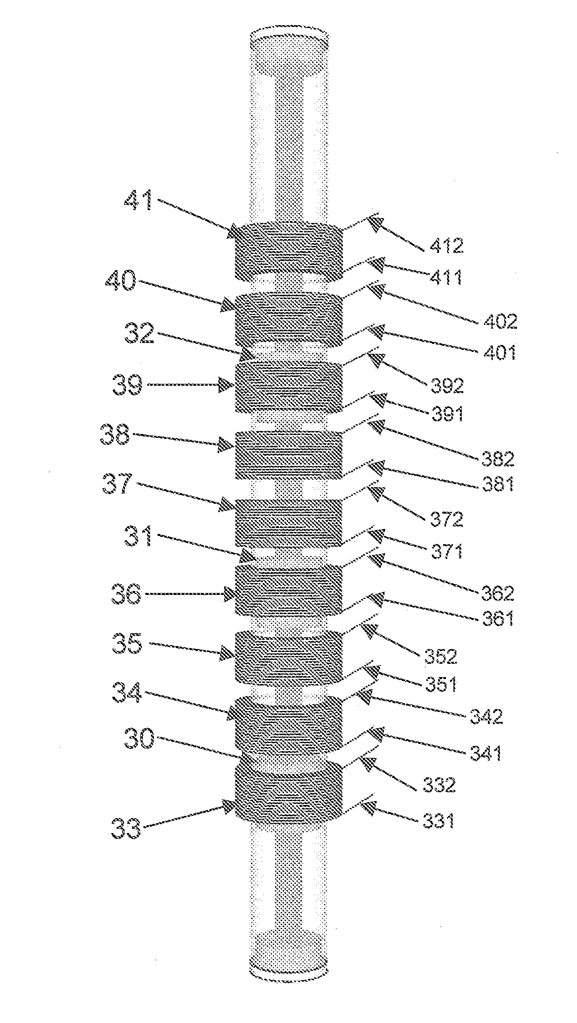
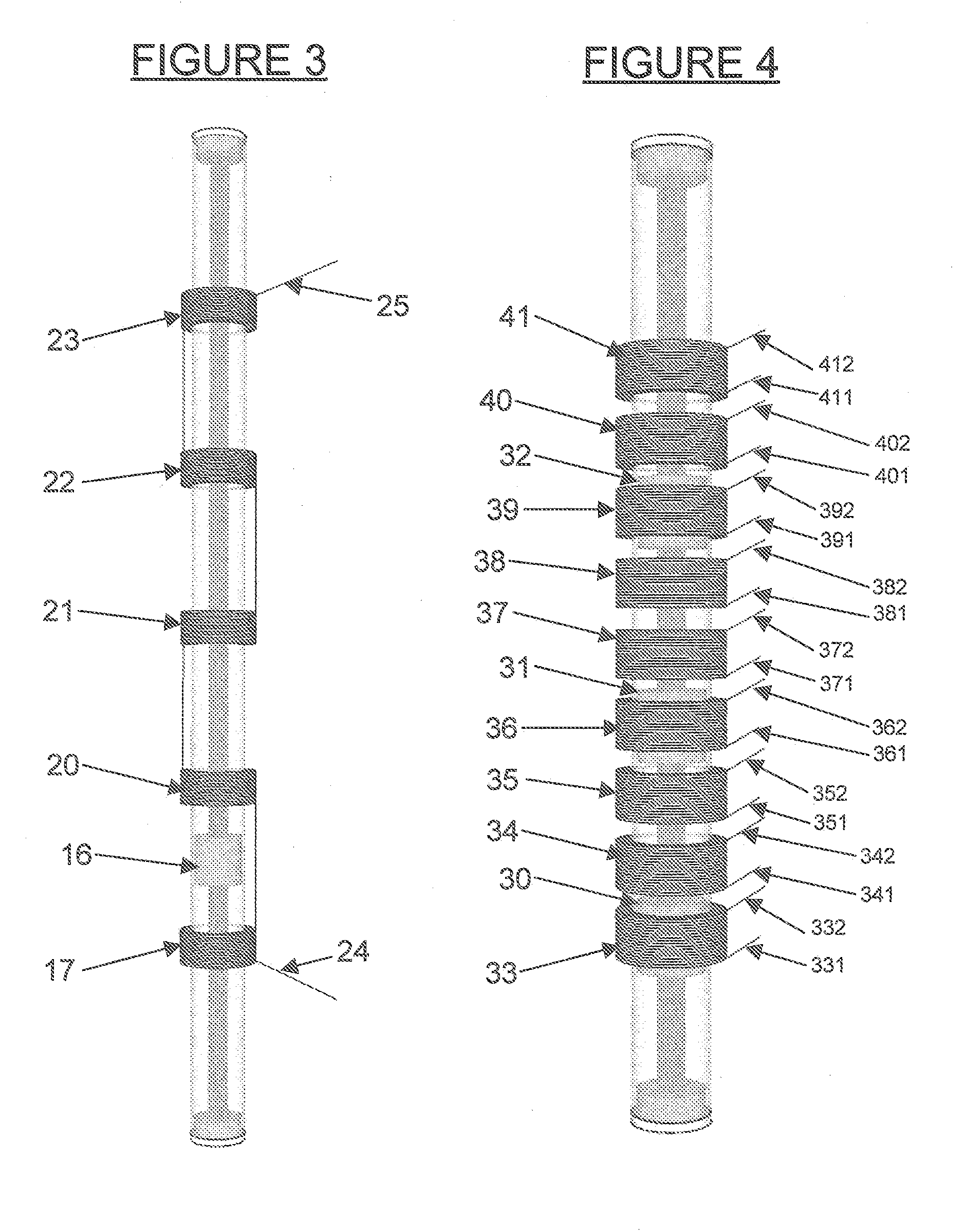
[0024]Recognizing that the magnetic field strength of permanent rare earth magnets is limited by the size and configuration of these magnets, it is possible to scale the l...


PUM


Abstract

A portable linear generator for use as a battery charging element inside a portable powered device using multiple permanent magnets arranged linearly with each magnet constrained to repel each nearest magnet, one of the magnets fixed at one or each end of the array, one or more of the magnets free to move along the axis of the array, a guide rod extending through the magnets having a low friction or low friction and diamagnetic surface, and coaxially wound coil or coils of magnet wire arranged to electrically connect outside the device.

Description

CROSS REFERENCE TO RELATED APPLICATIONS[0001]Not ApplicableSTATEMENT REGARDING FEDERALLY SPONSORED RESEARCH OR DEVELOPMENT[0002]Not ApplicableDESCRIPTION OF ATTACHED APPENDIX[0003]Not ApplicableBACKGROUND OF THE INVENTION[0004]This invention relates generally to the field of generating electrical energy for portable battery charging and more specifically to a portable kinetic energy to electrical energy conversion device using repelling magnets.[0005]Rare earth permanent magnets have become very common, varied in size and strength, and inexpensive. They are most often used in simple scientific experiments or in applications requiring temporary attachment of papers to magnetic surfaces, or as clasps in handbags or cabinets, or other applications. More recently, these magnets have found use in “shaker” or Faraday flashlights. These devices make use of magnetic induction, human energy, and the new generation of white light emitting diodes that produce much more light from less energy t...

Claims


Application Information

Patent Timeline
Patent Type & Authority Applications(United States)
IPC IPC(8): H02K35/02
CPCH02K35/02
Inventor ISAACS, BLAKE L.
Owner GENNEO
Why Eureka
Try Eureka