Electric machine having a stator winding with rigid bars, and related method of construction

a stator winding and electric machine technology, applied in the direction of windings, dynamo-electric components, synchronous machines, etc., can solve the problems of difficult automatic telescope of coils inside the stator slots, damage to the external insulating enamel that covers, and complex construction methods, etc., to achieve easy and fast acquisition, easy and affordable, and easy to automate

Active Publication Date: 2012-05-03
MARELLI EURO SPA
View PDF10 Cites 23 Cited by
  • Summary
  • Abstract
  • Description
  • Claims
  • Application Information

AI Technical Summary

Benefits of technology

[0013]One advantage of the electric machine having a stator winding with rigid bars and method of construction of the electric machine of the invention is that it is easy and affordable to obtain.
[0014]Another advantage of the electric machine having a stator winding with rigid bars and method of construction of the electric machine of the invention is that electrical paths of the stator winding are easily and quickly obtained and easily automatable.
[0015]Another advantage of the electric machine having a stator winding with rigid bars and method of construction of the electric machine of the invention is that it can decrease stresses to which the bars are subjected during insertion, thus avoiding possible damage to external insulating enamel that coats the bars.
[0016]Another advantage of the electric machine having a stator winding with rigid bars and method of construction of the electric machine of the invention is that each bar is individually pushed and, hence, it is possible to accurately calibrate maximum pushing force exercisable on the bar and apply small corrections to a “pushing” direction to consider certain specificities of the bar.
[0017]Another advantage of the electric machine having a stator winding with rigid bars and method of construction of the electric machine of the invention is that it improves quality of the corresponding internal folds of the double folds of the legs.

Problems solved by technology

Such a construction method is complex to automate as it is very difficult to automatically telescope the coils inside the stator slots as the coils do not have a stable shape and should be deformed to pass through the small axial aperture of the slots.
However, differentiating the sizes of the cusps of the “U”-shaped bars involves significant complications both in making the “U”-shaped bars (as at least two different types of “U”-shaped bars should be made) and inserting the “U”-shaped bars into the stator slots (as there is a need to manage at least two different types of “U”-shaped bars that have to be telescoped into accurate and predetermined positions and are in no way interchangeable with each other).
However, a push of high intensity is simultaneously exercised on all the “U”-shaped bars, and, hence, it is possible that one or more “unfortunate”“U”-shaped bars is / are subjected to an excessive push (i.e., too strong) and / or improperly directed, which induces damage to the external insulating enamel that covers the “U”-shaped bars themselves.

Method used


Image

  • Electric machine having a stator winding with rigid bars, and related method of construction
  • Electric machine having a stator winding with rigid bars, and related method of construction
  • Electric machine having a stator winding with rigid bars, and related method of construction

Examples


Embodiment Construction

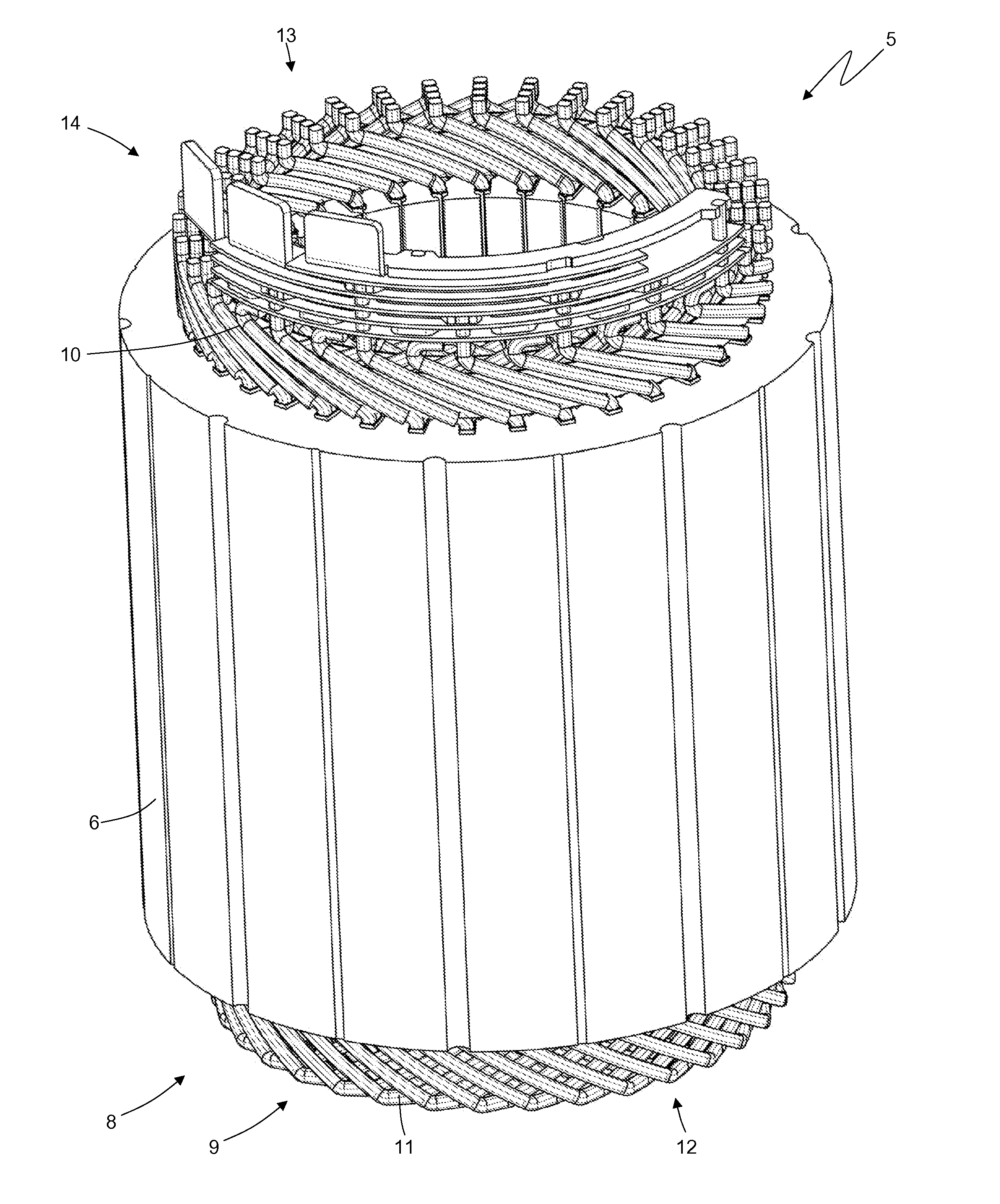
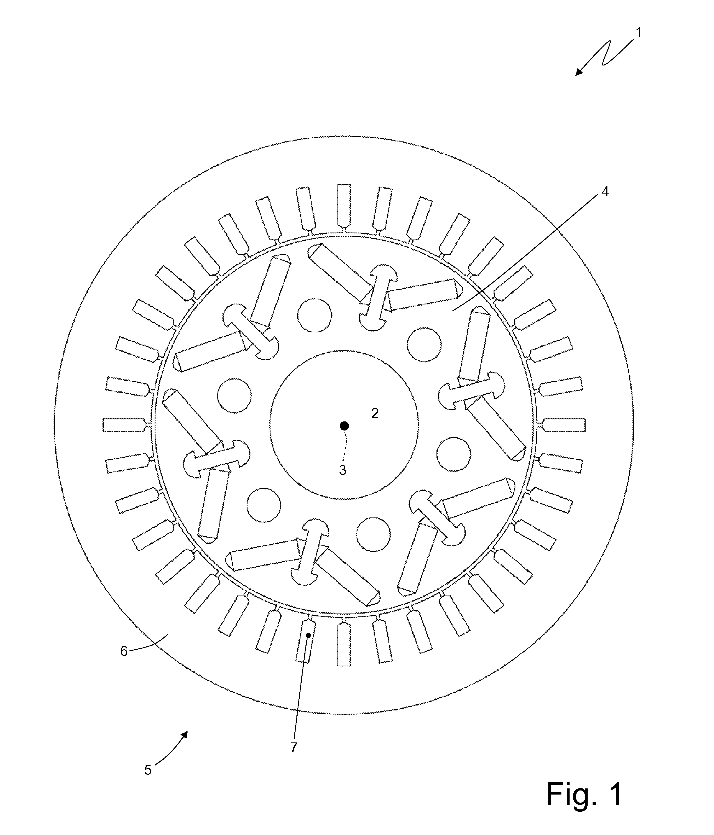
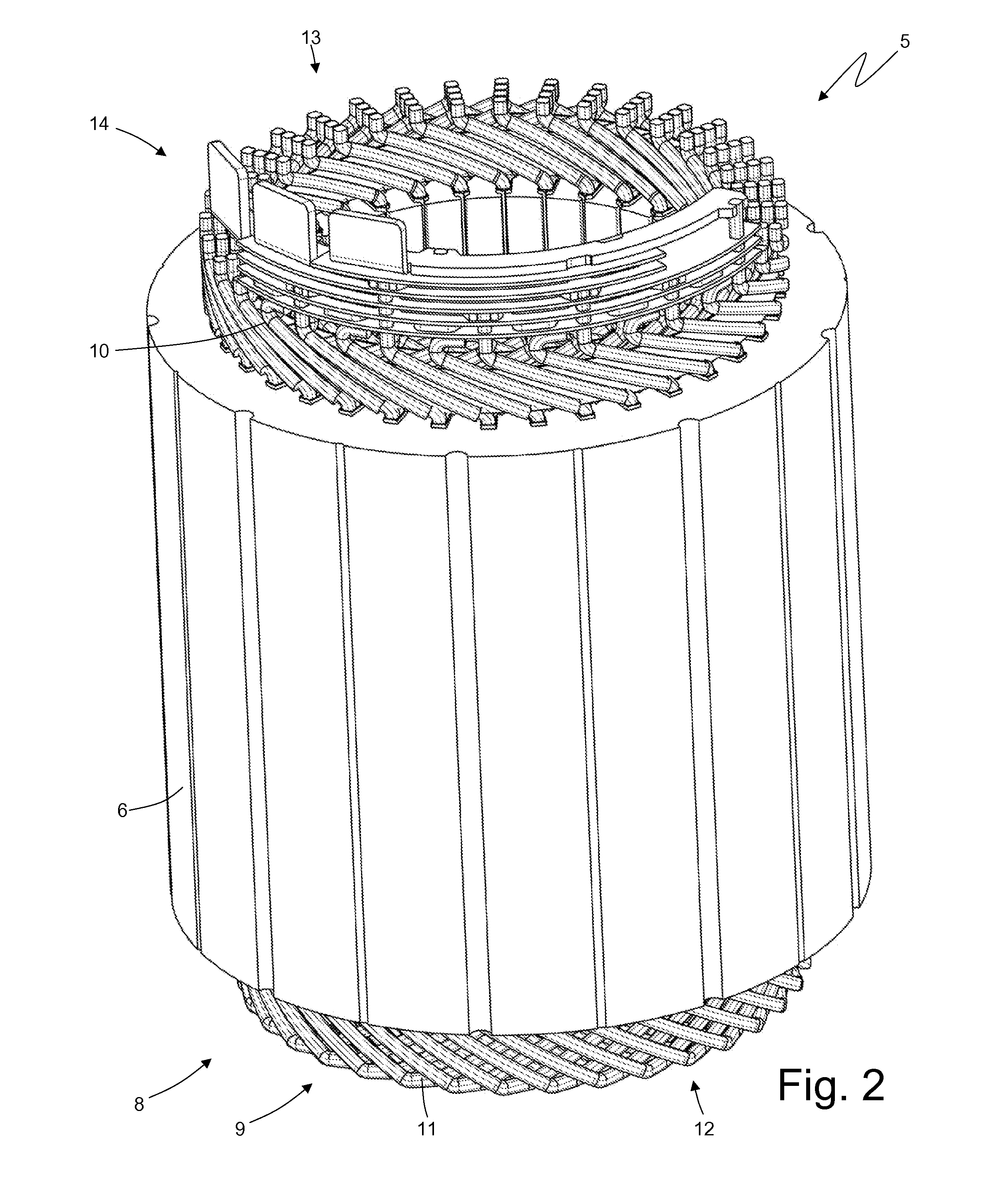
[0029]In FIG. 1, a synchronous electric machine is generally indicated at 1 for auto-traction of reversible type [i.e., it may operate both as an electric motor (by absorbing electrical power and generating a mechanical driving torque) and electric generator by absorbing mechanical energy and generating electrical power]. The electric machine 1 includes a shaft 2, which is rotatably mounted to rotate about a central axis of rotation 3, a rotor 4 with permanent magnets keyed to shaft 2 to rotate together with shaft 2 itself, and a cylindrical tubular stator 5 arranged about rotor 4 to enclose rotor 4 itself therein.

[0030]Stator 5 includes a magnetic core 6 that consists of a series of sandwiched sheets and has a centrally-holed tubular shape. The magnetic core 6 is longitudinally crossed by thirty-six stator slots 7 that are uniformly distributed along the internal side of the magnetic core 6 and accommodate a three-phase stator winding 8 (illustrated in FIG. 2). In the embodiment il...


PUM

PropertyMeasurementUnit
widthaaaaaaaaaa
electrically insulatingaaaaaaaaaa
phaseaaaaaaaaaa

Abstract

An electric machine includes a stator having a magnetic core crossed longitudinally by a stator slot and stator winding having a phase and series of rigid, U-shaped bars inserted through the slot. The slot defines “entry” and “exit” sides in which cusps and legs of the bars are placed. The legs coming out the “exit” side are twisted through relative double folds each of which defines internal and external folds in opposite directions. Ends of the legs are electrically connected to each other to form electrical paths of the winding. A width of the cusps is identical for the bars. The ends of a pair in a part of the winding are initially not adjacent to each other and folded toward each other to be arranged parallel to each other in a circumferential direction so that the ends touch each other to allow an electrical connection between the ends.

Description

REFERENCE TO RELATED APPLICATION[0001]This application claims benefit of the filing date of and priority to Italian Patent Application BO2010A 000583 filed on Sep. 29, 2010.BACKGROUND OF INVENTION[0002]1. Field of Invention[0003]The invention relates, generally, to an electric machine and, more particularly, to such a machine that has a stator winding with rigid bars and a method of construction thereof.[0004]2. Description of Related Art[0005]Traditionally, the stator winding of an electric machine is made by filiform and flexible conductors that are initially coil-wound. Then, the coils are telescoped into the stator slots and are, hence, electrically connected to one another. Such a construction method is complex to automate as it is very difficult to automatically telescope the coils inside the stator slots as the coils do not have a stable shape and should be deformed to pass through the small axial aperture of the slots.[0006]To overcome the construction difficulties of the st...

Claims


Application Information

Patent Timeline
Patent Type & Authority Applications(United States)
IPC IPC(8): H02K3/28H02K15/08H02K3/38
CPCH02K3/12H02K3/505H02K2211/03Y10T29/49009
Inventor COMINETTI, PAOLOCIAMPOLINI, FRANCOGIORGIANNI, VINCENZO
Owner MARELLI EURO SPA
Why Eureka
Try Eureka