Surface acoustic wave resonator, surface acoustic wave oscillator, and surface acoustic wave module device

a technology of surface acoustic wave and oscillator, which is applied in the direction of piezoelectric/electrostrictive/magnetostrictive devices, piezoelectric/electrostrictive/magnetostrictive machines, and oscillation circuit power consumption increase, etc., to achieve stable oscillation of surface acoustic waves and low power consumption

Inactive Publication Date: 2012-05-03
SEIKO EPSON CORP
View PDF5 Cites 5 Cited by
  • Summary
  • Abstract
  • Description
  • Claims
  • Application Information

AI Technical Summary

Benefits of technology

[0009]According to the structure, the IDT, in which the line occupation rate at which the electromechanical coupling coefficient becomes the maximum is different from the line occupation rate at which the reflection of a surface acoustic wave becomes the maximum, is divided into three regions, and the three regions are weighted by the electrode finger interval and the line occupation rate. Each of the first, second, and third regions of the IDT has a uniform electrode finger interval, and the electro finger intervals in the second and third regions are formed larger than that in the first region. The first region has a first line occupation rate, the second region has a second line occupation rate, and the third regions has a third line occupation rate, and the first, second and third line occupation rates are uniform in the first, second, and third regions respectively, and an electromechanical coupling coefficient at the first line occupation rate is larger than the electromechanical coupling coefficients at the second line occupation rate and the third line occupation rate, and the reflection of the surface acoustic wave at the second line occupation rate and the third line occupation rate is larger than the reflection of the surface acoustic wave at the first line occupation rate. A standing wave of a surface acoustic wave generated in the surface acoustic wave resonator has large oscillation displacement in the first region, which is the center of the IDT. On the other hand, the standing wave has small oscillation displacement in the second and third regions, which are opposite sides of the IDT. In the first region having large oscillation displacement, a line occupation rate is selected at which the electromechanical coupling coefficient becomes large in order to suppress an increase in a CI value. On the other hand, in the second and third regions having small oscillation displacement, a line occupation rate is selected at which reflection of a surface acoustic wave becomes large in order to enhance the oscillation energy confinement effect. Accordingly, the surface acoustic wave resonator having excellent CI value and Q value can be realized. As a result, the surface acoustic wave resonator can be downsized while the Q value is improved, and the surface acoustic wave resonator having low power consumption can be provided by decreasing the CI value.
[0015]According to the structure, the surface acoustic resonator can be provided that exhibits excellent frequency temperature characteristics and whose Q value is increased and whose CI value is reduced by using an in-plane rotated ST cut quartz substrate having the Euler angle of (−1° to +1°, 113° to 135°, ±(40° to) 49°), setting a value of the first line occupation rate in a range of 0.35 or more to 0.5 or less, and setting values of the second line occupation rate and the third line occupation rate less than 0.35.
[0017]According to the structure, the surface acoustic resonator can be provided that exhibits excellent frequency temperature characteristics and whose Q value is increased and whose CI value is reduced by using an in-plane rotated ST cut quartz substrate having the Euler angle of (−1° to +1°, 113° to 135°, ±(40° to) 49°), setting a value of the first line occupation rate in a range of 0.4 or more to 0.6 or less, and setting values of the second line occupation rate and the third line occupation rate more than 0.6.
[0019]According to the structure, since the surface acoustic wave resonator whose Q value is increased and whose CI value is decreased is mounted, an oscillation of a surface acoustic wave is stable. As a result, the surface acoustic wave oscillator having low power consumption can be provided.
[0021]According to the structure, since the surface acoustic wave resonator whose Q value is increased and whose CI value is decreased is mounted, an oscillation of a surface acoustic wave is stable. As a result, the surface acoustic wave oscillator having low power consumption can be provided.

Problems solved by technology

Thereby, characteristics of the surface acoustic wave resonator cannot be substantially obtained.
The decrease in the Q value blocks excitation of a stable surface acoustic wave while the increase in the CI value causes an increase in power consumption in an oscillation circuit.

Method used


Image

  • Surface acoustic wave resonator, surface acoustic wave oscillator, and surface acoustic wave module device
  • Surface acoustic wave resonator, surface acoustic wave oscillator, and surface acoustic wave module device
  • Surface acoustic wave resonator, surface acoustic wave oscillator, and surface acoustic wave module device

Examples


first embodiment

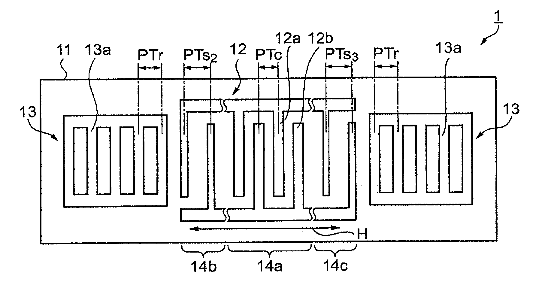
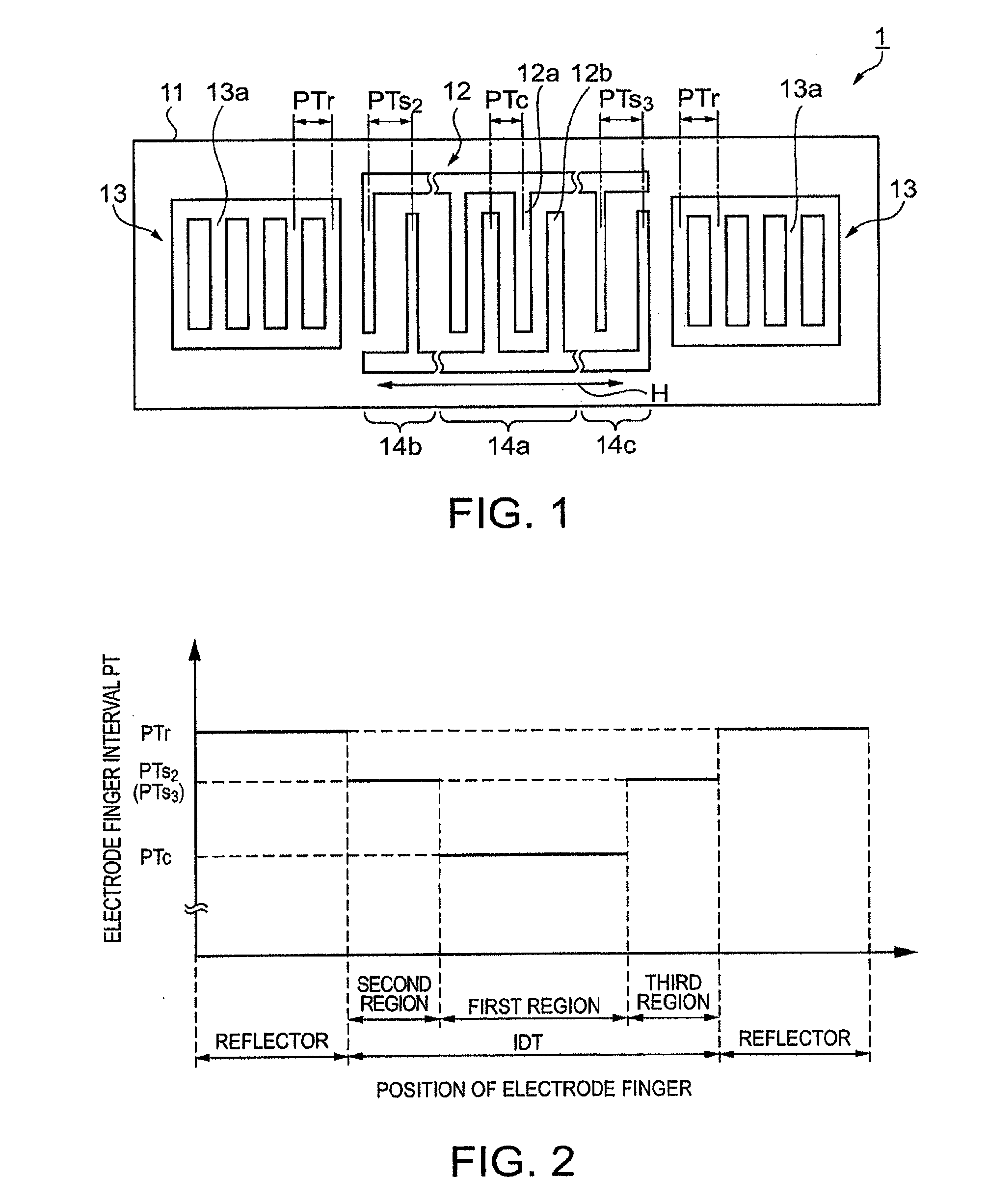
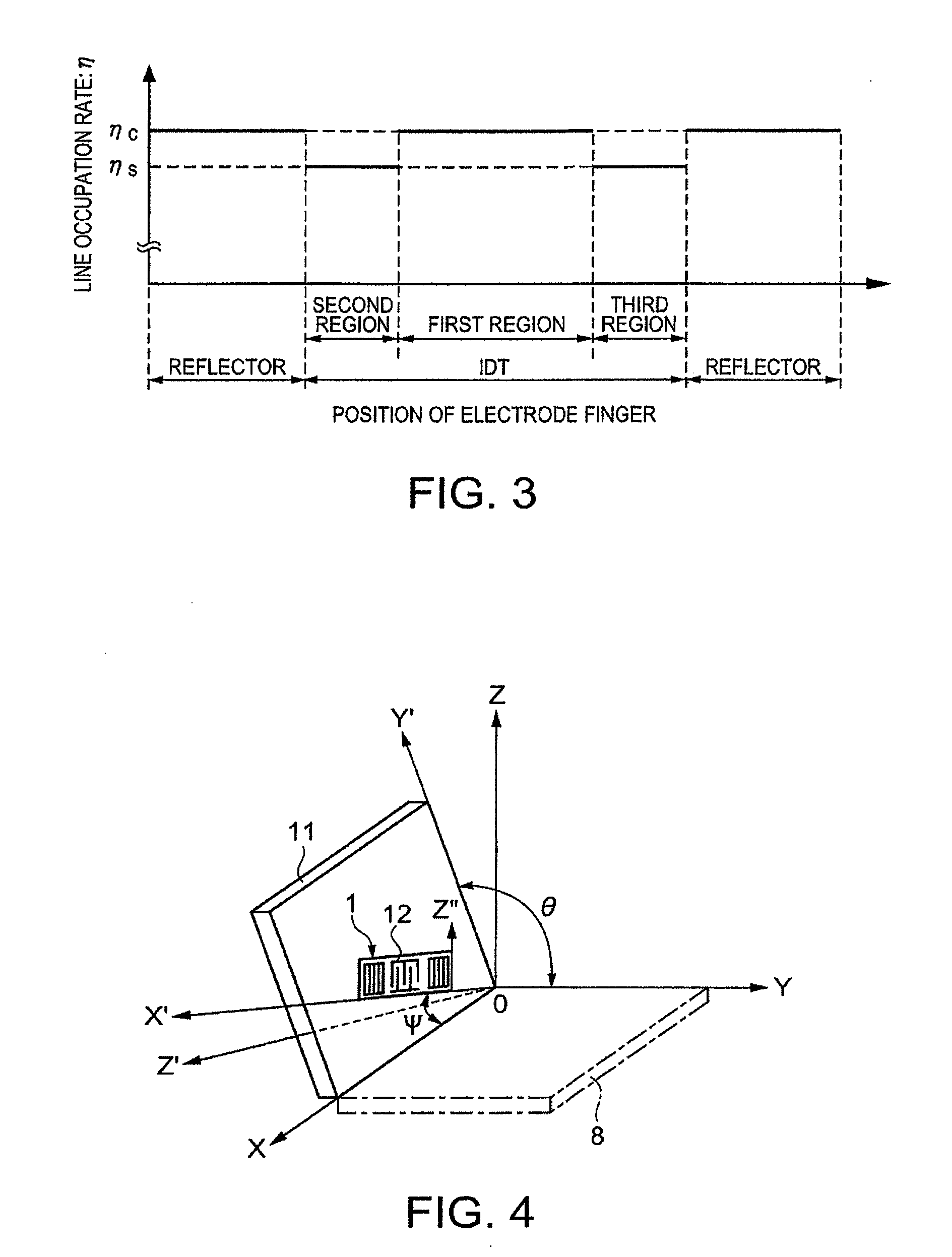
[0042]Next, a first embodiment of the invention will be described. FIG. 1 is a plan view schematically illustrating a structure of the surface acoustic wave resonator of the present embodiment. FIG. 2 is a diagram illustrating a relationship between a position of the electrode finger and the electrode finger interval. FIG. 3 is a diagram illustrating a relationship between the position of the electrode finger and the line occupation rate. FIG. 4 is a diagram illustrating a cutout angle of a quartz substrate and a surface acoustic wave propagation direction thereof.

[0043]As FIG. 1 shows, a surface acoustic wave resonator 1 includes an IDT 12 composed of interdigital electrodes and a pair of reflectors 13 formed in a manner sandwiching the IDT 12 in the propagation direction of a surface acoustic wave. The IDT 12 and the reflectors 13 are arranged on a quartz substrate 11 serving as a piezoelectric substrate. In the surface acoustic wave resonator 1, a surface acoustic wave excited by...

second embodiment

[0056]A surface acoustic wave resonator of a second embodiment will be described. In the present embodiment, the surface acoustic wave propagation direction of the quartz substrate and values of the line occupation rate thereof are different from those in the first embodiment. The quartz substrate is made of an in-plane rotated ST cut quartz substrate whose cut surface and whose surface acoustic wave propagation direction are (−1° to +1°, 113° to 135°, −3° to 3°) when they are expressed by the Euler angle (φ, θ, Ψ). In the surface acoustic wave resonator, the IDT is arranged in a manner that the propagation direction of a surface acoustic wave is in the X axis (Ψ=0°±3°). Further, the electrode fingers intervals in each region of the IDT is the same as those in the first embodiment (refer to FIGS. 1 and 2), and descriptions of the structure of the surface acoustic wave resonator will be omitted.

[0057]FIG. 9 is a graph illustrating a relationship between the line occupation rate and e...

third embodiment

[0061]By mounting the surface acoustic wave resonator of any of the embodiment in a package, a surface acoustic wave oscillator can be configured. FIG. 11 is a sectional view schematically illustrating a surface acoustic wave oscillator including the surface acoustic wave resonator mounted in a package. A surface acoustic wave oscillator 30 includes a ceramic package 31, an IC chip 32, the surface acoustic wave resonator 1, a lid 37, and the like. Formed in the ceramic package 31 is a recess 38 that is opened. Formed in the ceramic package 31 is a seam ring 35 in a manner surrounding the recess 38. The seam ring 35 is formed of a metal material such as kovar. In addition, on the periphery surface of the ceramic package 31, an external connection electrode 36 is formed to make connection with the external such as a circuit substrate. Though it is not illustrated in the drawing, wiring lines are provided so as to couple the external connection electrode 36 to the inside of the recess ...


PUM


Abstract

A surface acoustic wave resonator includes a piezoelectric substrate and an interdigital transducer (IDT) that includes electrode fingers exciting a surface acoustic wave on the piezoelectric substrate, a first region at a center of the IDT, and a second region and a third region at opposite sides of the IDT. In the IDT, a line occupation rate at which an electromechanical coupling coefficient becomes a maximum is different from the line occupation rate at which reflection of the surface acoustic wave becomes a maximum.

Description

BACKGROUND[0001]This is a Continuation of application Ser. No. 12 / 603,225 filed Oct. 21, 2009, which claims the benefit of Japanese Patent Application No. 2008-273971 filed Oct. 24, 2008. The disclosure of the prior applications is hereby incorporated by reference herein in its entirety.[0002]1. Technical Field[0003]The present invention relates to a surface acoustic wave resonator using a piezoelectric substrate, a surface acoustic wave oscillator, and a surface acoustic wave module device.[0004]2. Related Art[0005]Surface acoustic wave resonators using a surface acoustic wave (SAW) have been widely used as electronic apparatuses. In recent years, along with the popularization of portable apparatuses, it is required to downsize the surface acoustic wave resonators, which are used for the portable apparatuses. If the number of pairs of interdigital transducer (ITD) is reduced for downsizing the surface acoustic wave resonator, a decrease in a Q value or an increase in a crystal impe...

Claims


Application Information

Patent Timeline
Patent Type & Authority Applications(United States)
IPC IPC(8): H03H9/25H03B5/32
CPCH03H9/02551H03H9/0547H03H9/1092H03H9/14547
Inventor YAMANAKA, KUNIHITO
Owner SEIKO EPSON CORP
Why Eureka
Try Eureka