
Video processing apparatus, imaging apparatus, video processing method, and storage medium

a video processing and imaging technology, applied in the field of video processing apparatus, imaging apparatus, video processing method, and storage medium, can solve the problems of significant time and labor, inability to adjust the imaging direction for the mask area setting, etc., and achieve the effect of not increasing labor and tim

Active Publication Date: 2012-05-03
CANON KK
View PDF6 Cites 17 Cited by
  • Summary
  • Abstract
  • Description
  • Claims
  • Application Information

AI Technical Summary

Benefits of technology

[0010]The video processing apparatus according to the present invention can appropriately superimpose a mask image on a mask area to be covered on a flat plane without increasing the labor and time required in performing mask area settings.

Problems solved by technology

However, in a case where the imaging direction of the imaging apparatus is fixed, it is unfeasible to adjust the imaging direction for the mask area setting.
Further, even in a case where the imaging direction is changeable, a significant amount of time and labor will be required if the direction of a camera is changed each time when the mask area setting is performed.

Method used


Image

  • Video processing apparatus, imaging apparatus, video processing method, and storage medium
  • Video processing apparatus, imaging apparatus, video processing method, and storage medium
  • Video processing apparatus, imaging apparatus, video processing method, and storage medium

Examples


Embodiment Construction

[0027]Various exemplary embodiments, features, and aspects of the invention will be described in detail below with reference to the drawings.

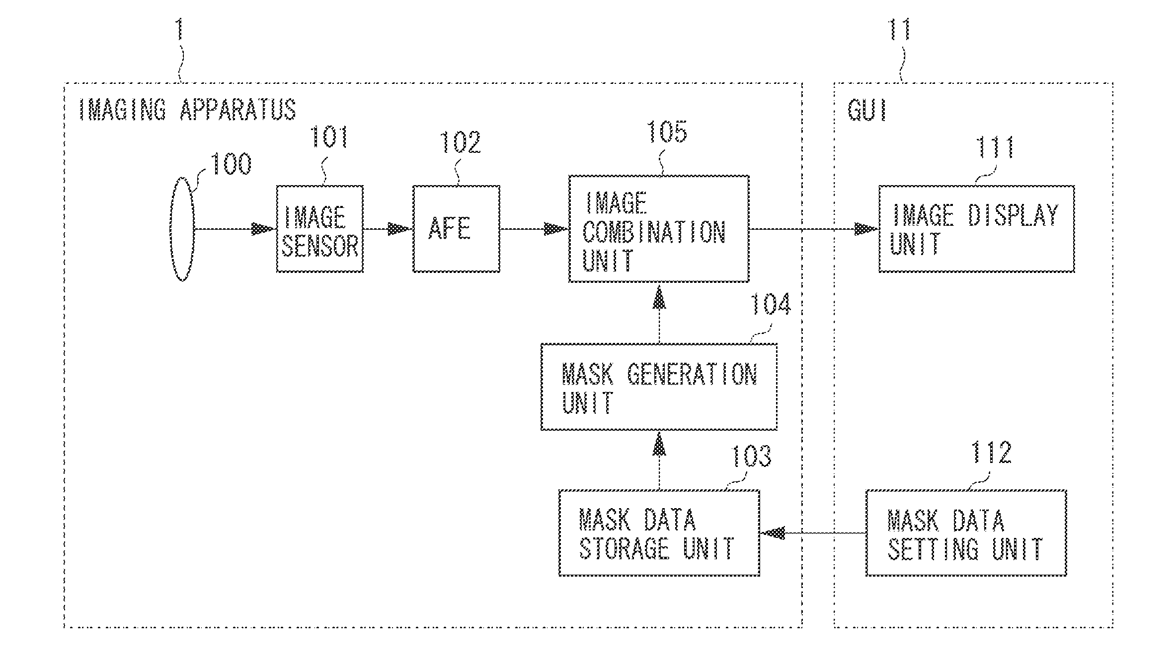
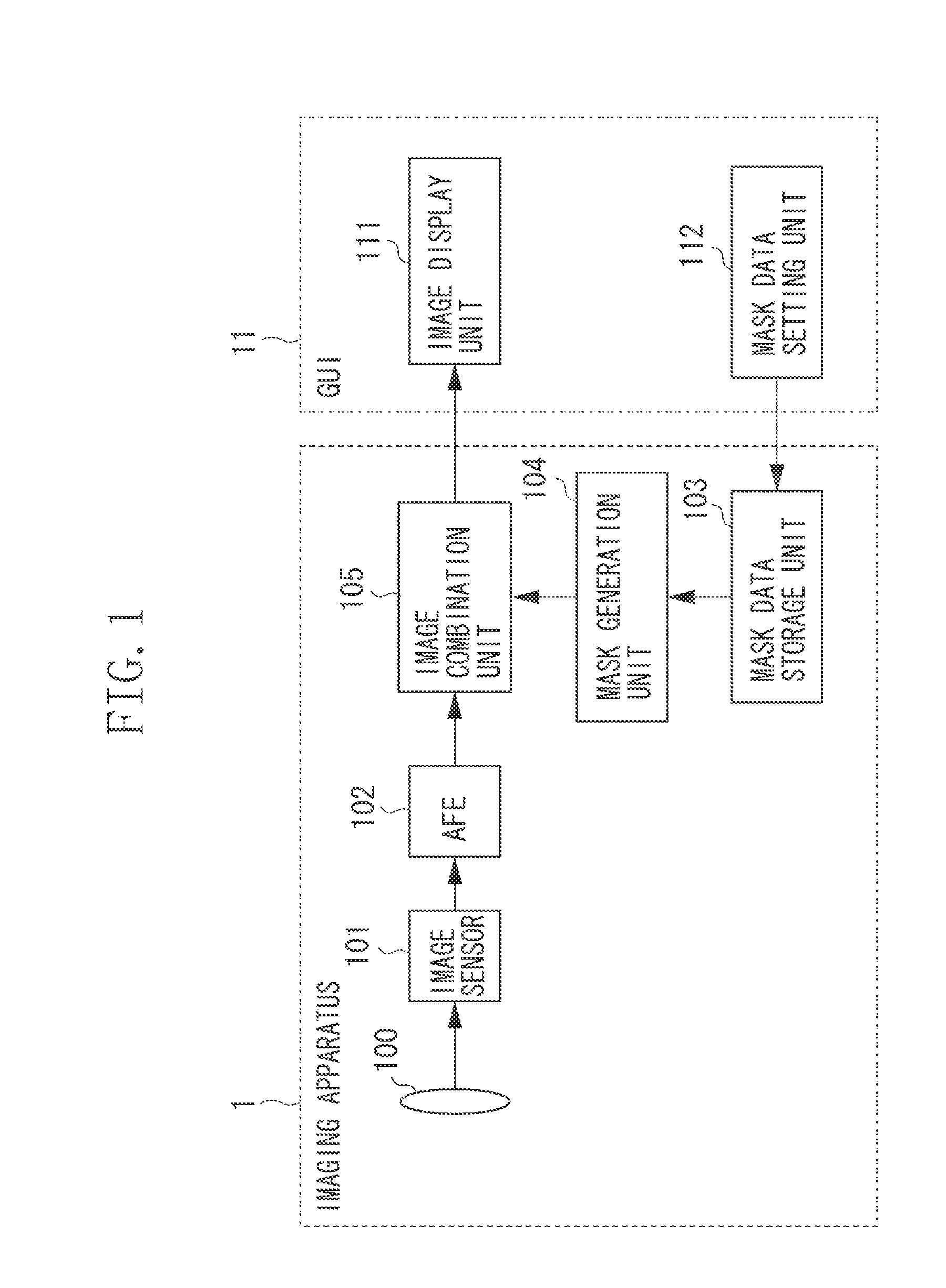
[0028]First, an example configuration of an imaging apparatus 1 according to a first exemplary embodiment of the present invention is described below with reference to FIG. 1. An imaging lens 100 causes incident light to focus on an image sensor 101. The image sensor 101 can generate an image signal representing a captured image having been focused by the imaging lens 100.

[0029]Analog Front End (AFE) 102 is an analog circuit that can convert an analog signal into a digital signal. The AFE 102 includes a circuit that can amplify the image signal generated by the image sensor 101 and can remove not only an amplification noise component but also a reset noise component included in the image signal. The AFE 102 can convert the image signal output from the image sensor 101 into a digital signal and can output a captured image to an image combination...


PUM


Abstract

A video processing method includes calculating mean values with respect to x coordinate value and y coordinate value of vertices that define a corresponding area, which is obtained when a designated area in spherical coordinates is projected on an xy coordinate plane that represents a captured image, and superimposing a mask image R on the captured image in such a way as to bring a point G having an x coordinate value and a y coordinate value identical to the calculated mean values with respect to the x coordinate value and the y coordinate value into coincidence with a point defined by a midpoint in the height direction and a midpoint in the width direction of the mask image.

Description

BACKGROUND OF THE INVENTION[0001]1. Field of the Invention[0002]The present invention relates to a video processing apparatus that can display a captured image together with a mask image superimposed at a mask area thereof, and further relates to an imaging apparatus, a video processing method, and a storage medium.[0003]2. Description of the Related Art[0004]There is a conventionally known masking technique capable of superimposing a mask image on a partial area of an image captured by an imaging apparatus to prevent a specific image portion on which the mask image is superimposed from being viewed.[0005]In general, an image capturing area (hereinafter, referred to as “imaging area”) of an imaging apparatus can be expressed as an area in spherical coordinates illustrated in FIG. 8A, in which the imaging apparatus is positioned at the center thereof, when the imaging apparatus faces a predetermined direction. Further, FIG. 8B illustrates a projected image obtainable when a captured ...

Claims


Application Information

Patent Timeline
Patent Type & Authority Applications(United States)
IPC IPC(8): H04N5/222
CPCG06T3/0031H04N5/772G06T3/06
Inventor KOGURE, KENTARO
Owner CANON KK
Learn More