Lighting system

a technology of light source and light source, applied in the field of light source system, can solve the problems of secular usage giving rise to fears of light different from the desired light distribution, material degradation, and reduced reflection efficiency, so as to suppress light loss, suppress power consumption and heat generation, and reduce the number of light-emitting elements

Active Publication Date: 2012-05-03
SHARP KK
View PDF10 Cites 18 Cited by
  • Summary
  • Abstract
  • Description
  • Claims
  • Application Information

AI Technical Summary

Benefits of technology

[0031]According to the lighting system of the present invention, since the existence of the louver allows the light radiated from the plurality of light-emitting elements to be diffused, reflection in a plurality of states need not be performed, and light loss can be suppressed to be smaller than that in the conventional constitution. This can reduce the number of light-emitting elements to be mounted and a drive current, and suppress power consumption and an amount of heat gen

Problems solved by technology

That is, since the light radiated from the elements needs to be reflected in two stages, there is a problem of inefficiency.
In this manner, when the metal material is used for the light control member 117, ther

Method used


Image

  • Lighting system
  • Lighting system
  • Lighting system

Examples


Embodiment Construction

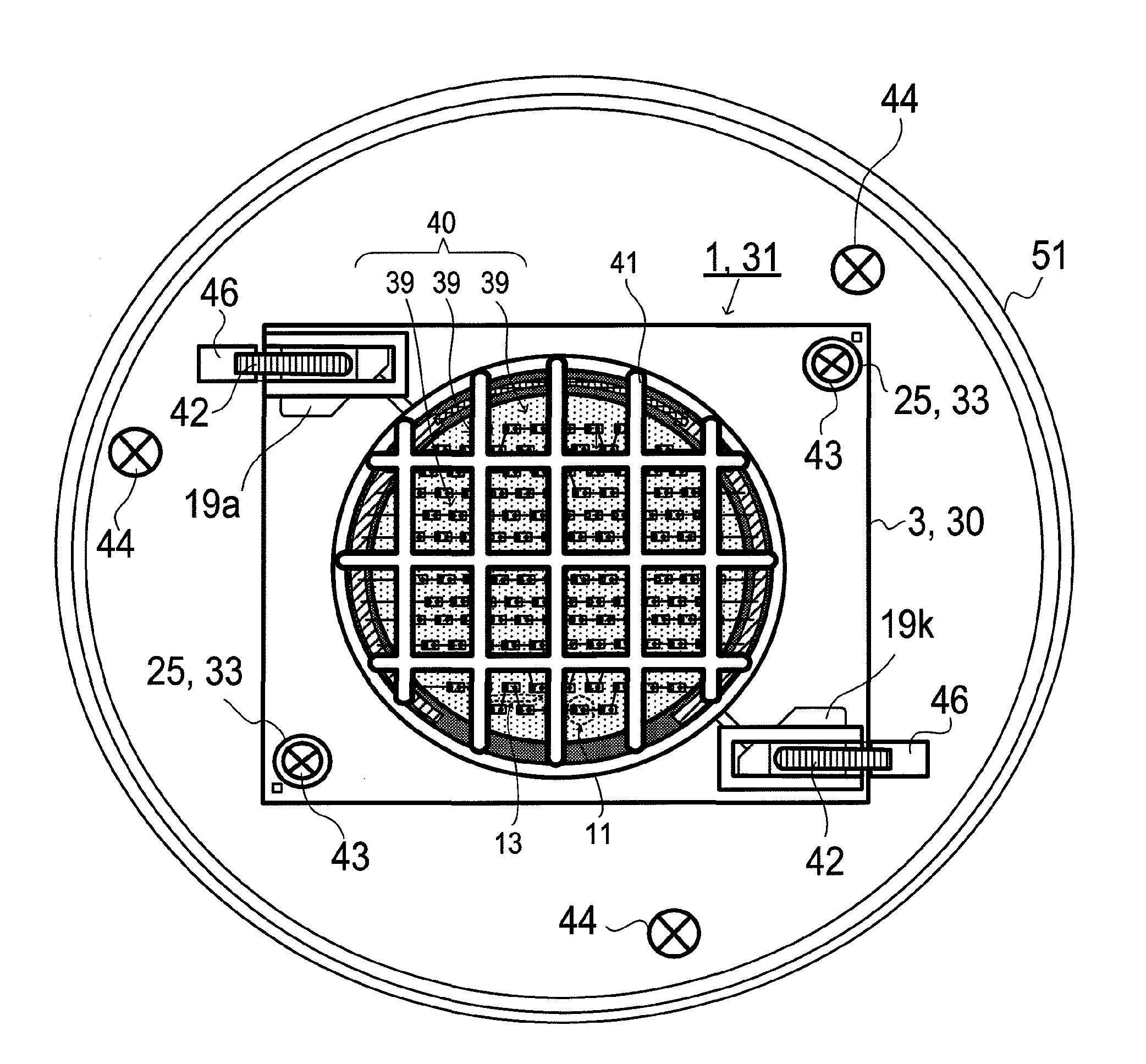
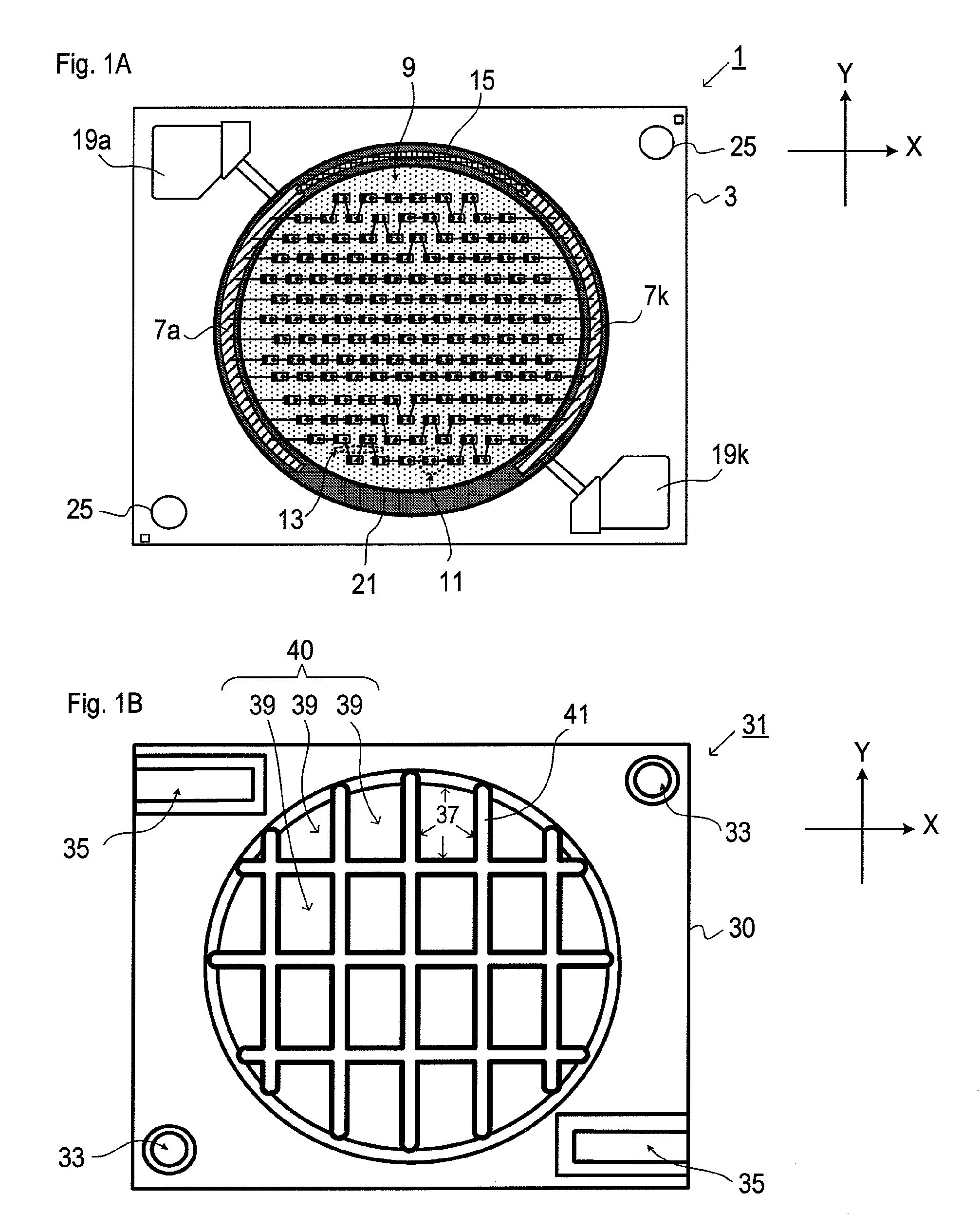
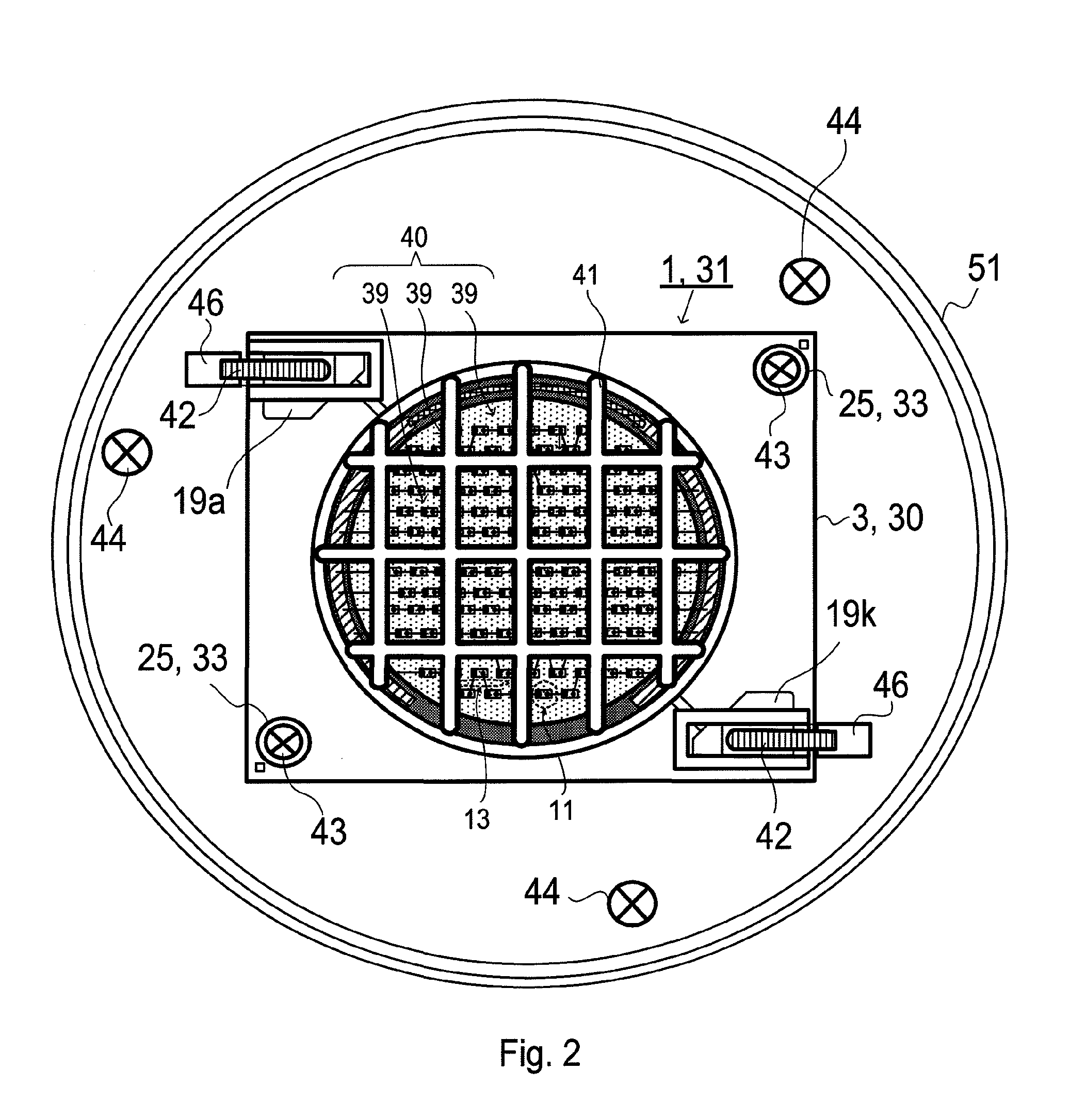
[0047]FIGS. 1A and 1B are schematic structure diagrams showing an example of a light-emitting device and a jig for light control included in a light system of the present embodiment. FIG. 1A shows the light-emitting device, and FIG. 1B shows the jig for light control.

[0048]As shown in FIG. 1A, a light-emitting device 1 included in the present lighting system includes a ceramic substrate 3, wiring patterns 7 (7a, 7k), a phosphor-containing resin layer 9, LED chips 11, wires 13, a printing resistive element 15, electrode lands for connector connection 19 (19a, 19k), a resin dam 21, and light-emitting device fixing holes 25 used at the time of positioning. In FIG. 1A, in order to make connection relations clear, an inside is made transparent to be shown.

[0049]Moreover, as shown in FIG. 1B, a jig for light control 31 included by the present lighting system is a jig to control radiated light from the LED chips 11 by being overlaid on the light-emitting device 1, and is made up of a resin...


PUM


Abstract

There is provided a lighting system capable of suppressing a decrease in light output while preventing occurrence of glare. The lighting system of the present invention includes a light-emitting device and a jig for light control. The light-emitting device includes a plurality of light-emitting elements arranged so as to be distributed on a substrate, and the jig for light control is made up of a resin plate having a plurality of discrete openings for light-emitting surface partitioned by a louver. The light-emitting device and the jig for light control are overlaid so that a light-emitting portion is exposed from the plurality of discrete openings for light-emitting surface.

Description

CROSS REFERENCE TO RELATED APPLICATION[0001]This Nonprovisional application claims priority under 35 U.S.C. §119(a) on Patent Application No. 2010-241486 filed in Japan on Oct. 27, 2010 the entire contents of which are hereby incorporated by reference.BACKGROUND OF THE INVENTION[0002]1. Field of the Invention[0003]The present invention relates to a lighting system, and particularly to a lighting system including a light-emitting device having light-emitting elements such as LEDs.[0004]2. Description of the Related Art[0005]Conventionally, there has been provided a light-emitting device with light-emitting elements mounted thereon. Particularly, when LED light sources are used as the light-emitting elements, anti-glare measures are important because directivity of light is high due to a structure thereof.[0006]In Japanese Patent Application Laid-Open No. 2004-265649 (hereinafter, referred to as publicly-known literature 1), and in Japanese Patent Application Laid-Open No. 2010-129501...

Claims


Application Information

Patent Timeline
IPC IPC(8): F21V21/00
CPCF21V11/06F21Y2105/10F21K9/232F21Y2115/10H01L2224/48137
Inventor HATA, TOSHIOISHIZAKI, SHINYAAGATANI, MAKOTO
Owner SHARP KK
Why Eureka
Try Eureka