Resilient mounting apparatus for low-ductility turbine shroud

Active Publication Date: 2012-05-03
GENERAL ELECTRIC CO
View PDF33 Cites 40 Cited by
  • Summary
  • Abstract
  • Description
  • Claims
  • Application Information

AI Technical Summary

Benefits of technology

[0007]This need is addressed by the present invention, which provides a resilient mounting apparatus for low-ductility turbine components, such as turbine shrouds. The axial position of the shroud may be determined at least in part by a spring element.
[0008]According to one aspect of the invention, a turbine flowpath apparatus for a gas turbine engine includes: a flowpath component exposed at least partially to a primary combustion gas flowpath of the engine, the flowpath component comprising low-ductility material; a metallic annular stationary structure surrounding the flowpath component; a first spring element disposed between the flowpath component and the stationary structure which resiliently urges the flowpath in a first axial direction; and a second spring element disposed between the flowpath component and the stationary structure which resiliently urges the flowpath component in a second axial direction in opposition to the first spring element.
[0009]According to another aspect of the invention, a turbine flowpath apparatus for a gas turbine engine includes: a flowpath component exposed at least partially to a primary combustion gas flowpath of the engine, the flowpath component comp

Problems solved by technology

However, differential thermal expansion between CMC components and the surrounding metallic hardware can change operating clearances and cause overconstraint, overloads, and / or loss of desired preload.

Method used


Image

  • Resilient mounting apparatus for low-ductility turbine shroud
  • Resilient mounting apparatus for low-ductility turbine shroud
  • Resilient mounting apparatus for low-ductility turbine shroud

Examples


Embodiment Construction

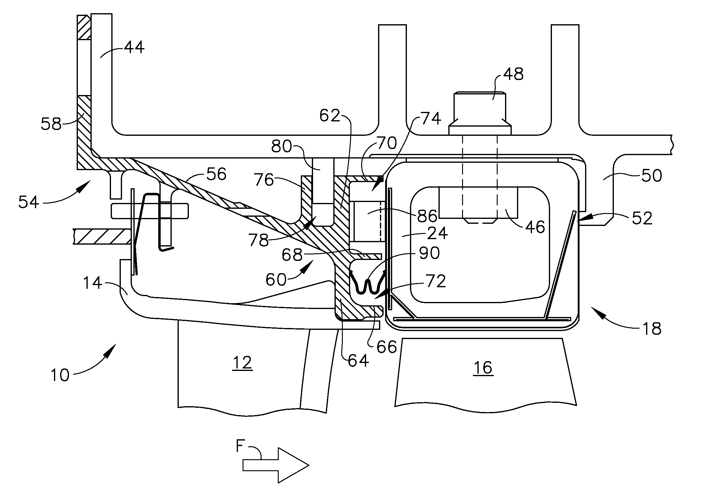
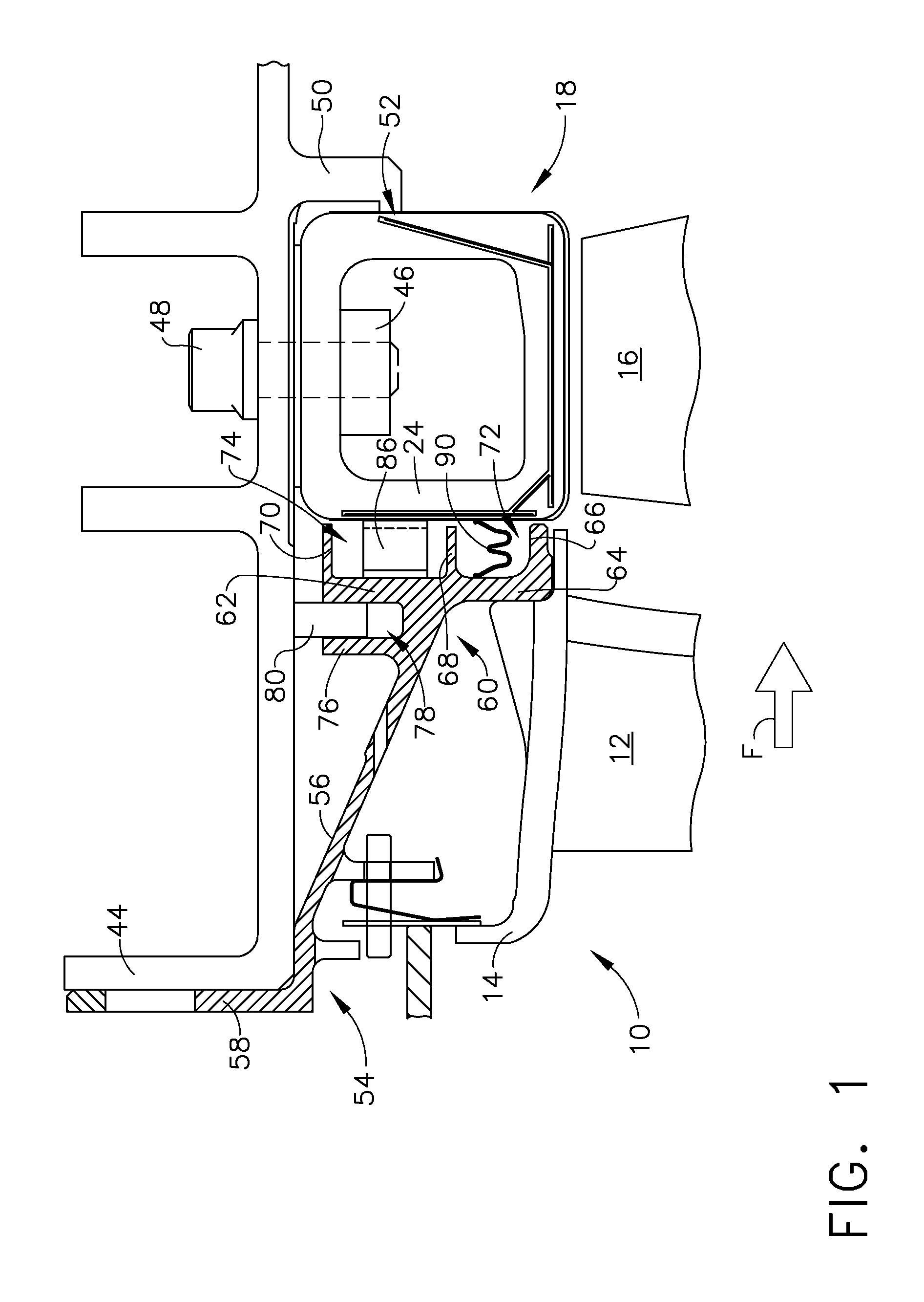
[0019]Referring to the drawings wherein identical reference numerals denote the same elements throughout the various views, FIG. 1 depicts a small portion of a high pressure turbine (“HPT”), which is part of a gas turbine engine of a known type. The function of the high pressure turbine is to extract energy from high-temperature, pressurized combustion gases from an upstream combustor (not shown) and to convert the energy to mechanical work, in a known manner. The high pressure turbine drives an upstream compressor (not shown) through a shaft so as to supply pressurized air to the combustor.

[0020]In the illustrated example, the engine is a turbofan engine and a low pressure turbine would be located downstream of the gas generator turbine and coupled to a shaft driving a fan. However, the principles described herein are equally applicable to turbojet and turboshaft engines, as well as turbine engines used for other vehicles or in stationary applications. Furthermore, while a turbine ...


PUM


Abstract

A turbine flowpath apparatus for a gas turbine engine includes: a flowpath component exposed at least partially to a primary combustion gas flowpath of the engine, the flowpath component comprising low-ductility material; a metallic annular stationary structure surrounding the flowpath component, including a bearing surface which bears against the flowpath component, so as to restrain the flowpath component from axial movement in a first direction; and a spring element disposed between the flowpath component and the stationary structure which resilient urges the flowpath component in the first direction against the bearing surface.

Description

BACKGROUND OF THE INVENTION[0001]This invention relates generally to gas turbine engines, and more particularly to apparatus and methods for mounting shrouds made of a low-ductility material in the turbine sections of such engines.[0002]A typical gas turbine engine includes a turbomachinery core having a high pressure compressor, a combustor, and a high pressure turbine in serial flow relationship. The core is operable in a known manner to generate a primary gas flow. The high pressure turbine (also referred to as a gas generator turbine) includes one or more rotors which extract energy from the primary gas flow. Each rotor comprises an annular array of blades or buckets carried by a rotating disk. The flowpath through the rotor is defined in part by a shroud, which is a stationary structure which circumscribes the tips of the blades or buckets. These components operate in an extremely high temperature environment, and must be cooled by air flow to ensure adequate service life. Typi...

Claims


Application Information

Patent Timeline
IPC IPC(8): F01D5/22
CPCF01D11/005F01D25/246F01D9/04F01D25/28Y02T50/672F01D25/26Y02T50/60
Inventor ALBERS, JOSEPHMARUSKO, MARKWILSON, BARRYDZIECH, AARONJOHNSON, CHRISTOPHER
Owner GENERAL ELECTRIC CO
Why Eureka
Try Eureka