Bicycle motor control system

Active Publication Date: 2012-05-03
SHIMANO INC
View PDF14 Cites 28 Cited by
  • Summary
  • Abstract
  • Description
  • Claims
  • Application Information

AI Technical Summary

Benefits of technology

[0025]In another aspect of the present invention, the tooth count of the sprocket corresponding to each shift position is stored in the memory device. Consequently, even if a sprocket of the external transmission device is changed to a sprocket having a different number of transmitting teeth, the propulsion force can be calculated based on the number of sprocket teeth by overwriting a tooth count stored in the memory device with a tooth count of the newly installed sprocket. As a result, even if a number of sprocket teeth is changed, the rate of the assistance force with respect to the propulsion force can be made equal for all shift positions and the motor can be driven at a constant assist ratio.
[0026]In another aspect of the present invention, the gear ratios of an internal transmission device are stored in correspondence to th

Problems solved by technology

As a result, it will not be possible to keep the assist ratio constant among the differen

Method used


Image

  • Bicycle motor control system
  • Bicycle motor control system
  • Bicycle motor control system

Examples


Embodiment Construction

[0040]Selected embodiments will now be explained with reference to the drawings. It will be apparent to those skilled in the art from this disclosure that the following descriptions of the embodiments are provided for illustration only and not for the purpose of limiting the invention as defined by the appended claims and their equivalents.

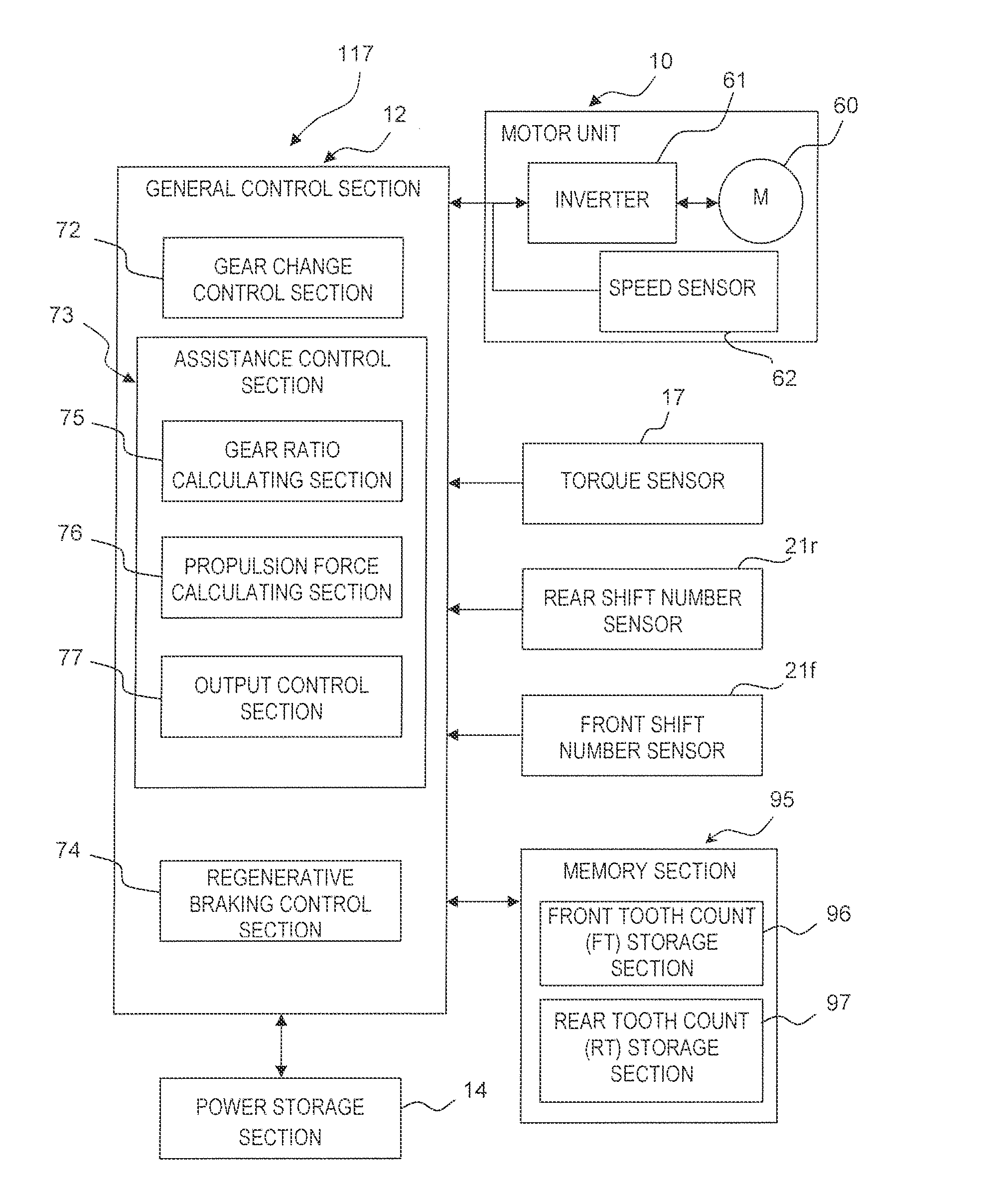
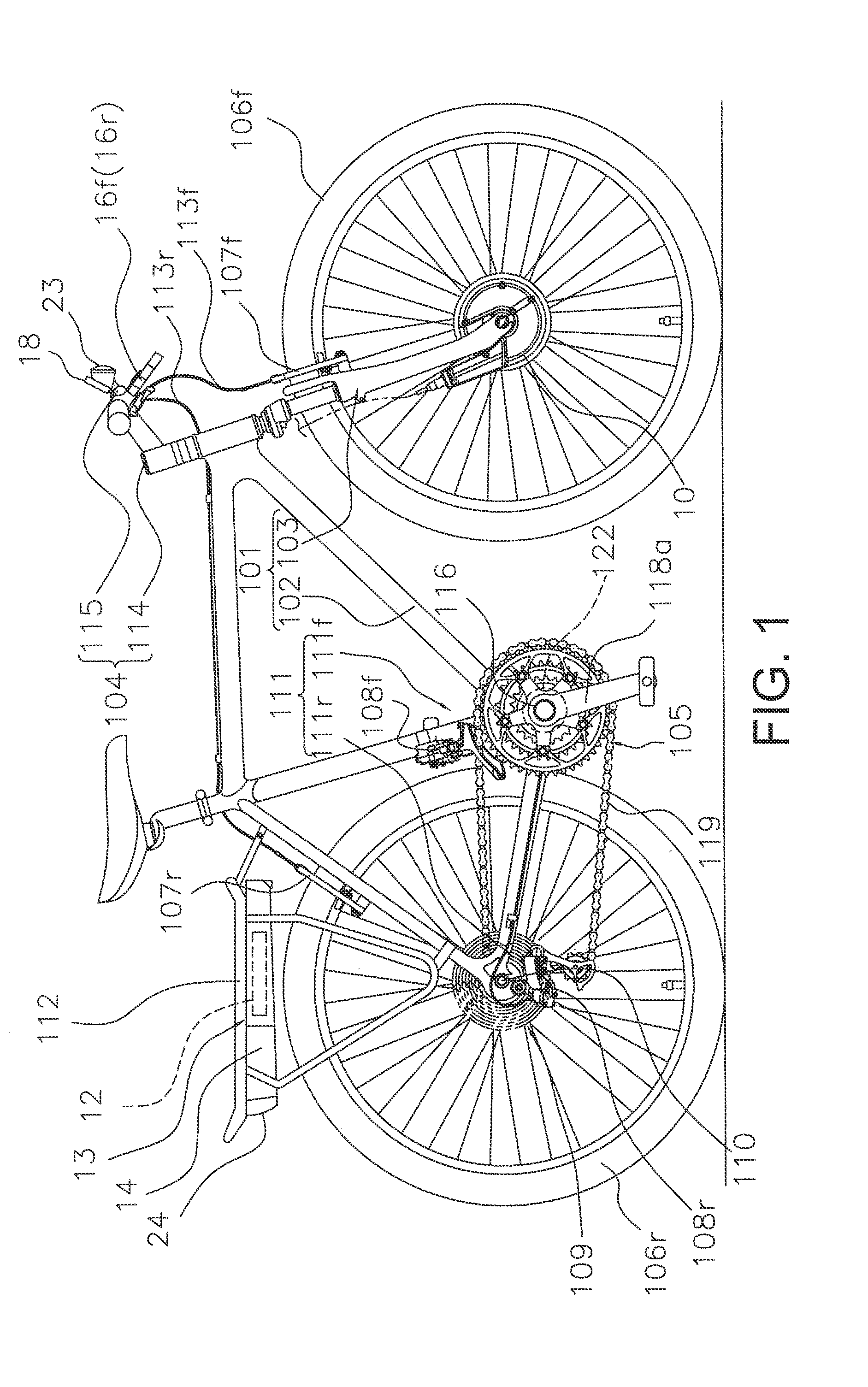
[0041]FIG. 1 shows an assisted bicycle according to a first embodiment of the present invention. This bicycle is configured to use a motor unit 10 to assist a drive force imparted by a rider. The motor unit 10 is controlled by a general control device 12. In the explanations that follow, the left and right directions of the bicycle are normally defined to be left and right directions observed when the bicycle is viewed from the rear.

[0042]The bicycle comprises a frame 101 having a frame body 102 and a front fork 103, a handlebar unit 104, a drive device 105, a front wheel 106f, a rear wheel 106r, a front brake device 107f, a rear brake device 107r...


PUM


Abstract

A bicycle motor control system is configured to control a drive assistance motor that can be installed on a bicycle having a drive force transmitting body. The bicycle motor control system comprises a memory device, a pedaling force detecting device, a propulsion force calculating section and a motor control section. The memory device stores a tooth count of a plurality of transmitting teeth of the drive force transmitting body. The pedaling force detecting device detects a pedaling force. The propulsion force calculating section calculates a propulsion force based on a pedaling force detected by the pedaling force detecting device and the tooth count of the transmitting teeth stored in the memory device. The motor control section controls the motor based on the propulsion force.

Description

CROSS-REFERENCE TO RELATED APPLICATIONS[0001]This application claims priority to Japanese Patent Application No. 2010-244337, filed on Oct. 29, 2010. The entire disclosure of Japanese Patent Application No. 2010-244337 is hereby incorporated herein by reference.BACKGROUND[0002]1. Field of the Invention[0003]This invention generally relates a motor control system. More specifically, the present invention relates to a bicycle motor control system that controls a drive assistance motor that can be installed on a bicycle having a drive force transmitting body on which a plurality of transmitting teeth are formed.[0004]2. Background Information[0005]In an assisted bicycle configured to use a motor to assist with pedaling of the bicycle, it is a known technology to have a motor control system that is provided with a transmission device and configured to control a motor assistance rate in accordance with a current shift position of the bicycle (e.g., see Japanese Laid-Open Patent Publicati...

Claims


Application Information

Patent Timeline
IPC IPC(8): B62M6/50B60L15/20G16Z99/00
CPCB60L15/2054B62M23/02B62M6/45B62M6/50B60L7/14B60L7/26B60L15/2009B60L2240/12B60L2240/421B60L2240/423B60L2250/12B60L2250/16B60L2250/24B60L1/14Y02T10/7044Y02T10/7005Y02T10/705Y02T10/7275Y02T10/645Y02T10/72B60L50/20B60L50/51B60L58/12B60L50/66G06F19/00B60L2200/12Y02T10/64Y02T10/70G16Z99/00
Inventor SAIDA, TAKAO
Owner SHIMANO INC
Why Eureka
Try Eureka