
Mower blade with replaceable inserts

a mower blade and insert technology, applied in the field of mower blades with replaceable inserts, can solve the problems of difficult removal of inserts, little if any advantage over conventional blade bars with integral cutting edges, and difficult chores, and achieve the effect of preventing (or preventing)

Inactive Publication Date: 2012-05-10
BLAREK JAMES A
View PDF0 Cites 29 Cited by
  • Summary
  • Abstract
  • Description
  • Claims
  • Application Information

AI Technical Summary

Benefits of technology

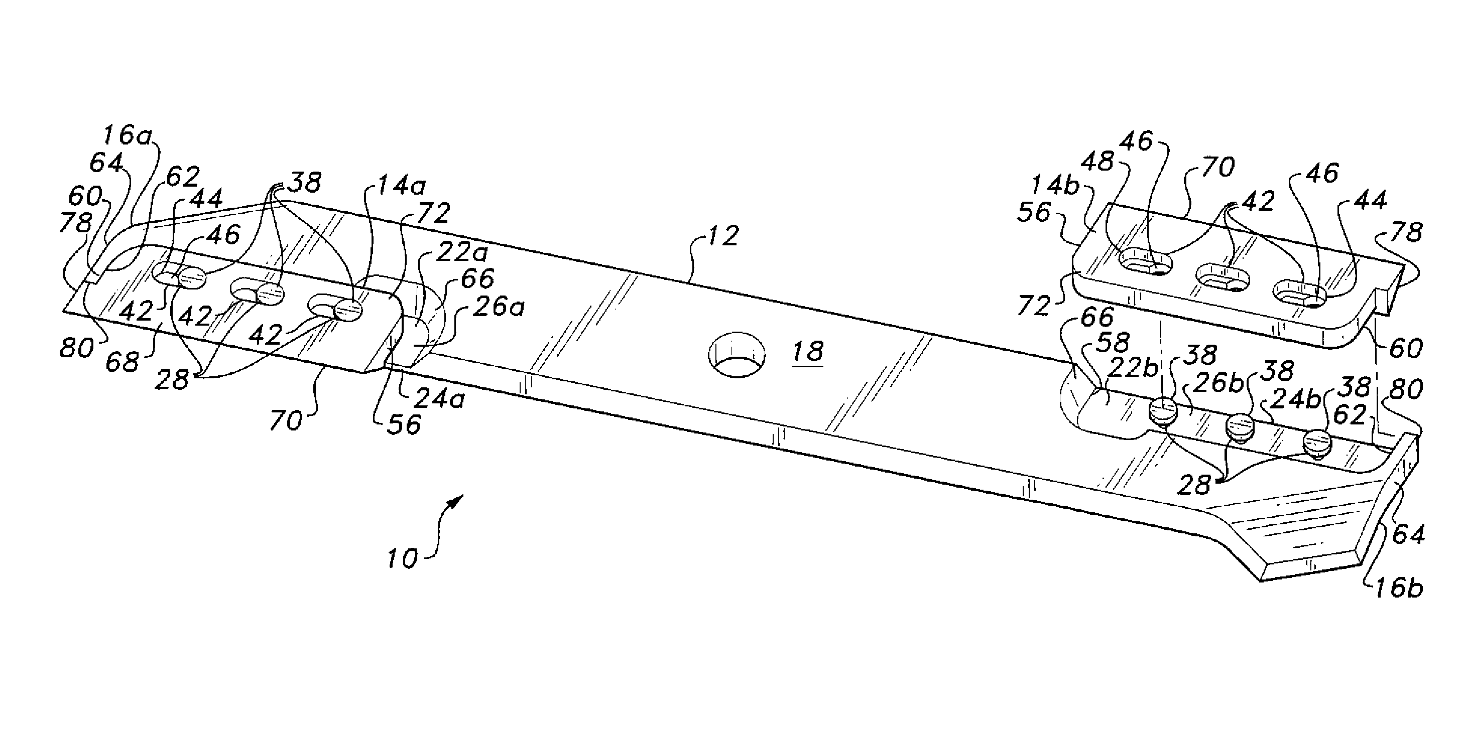
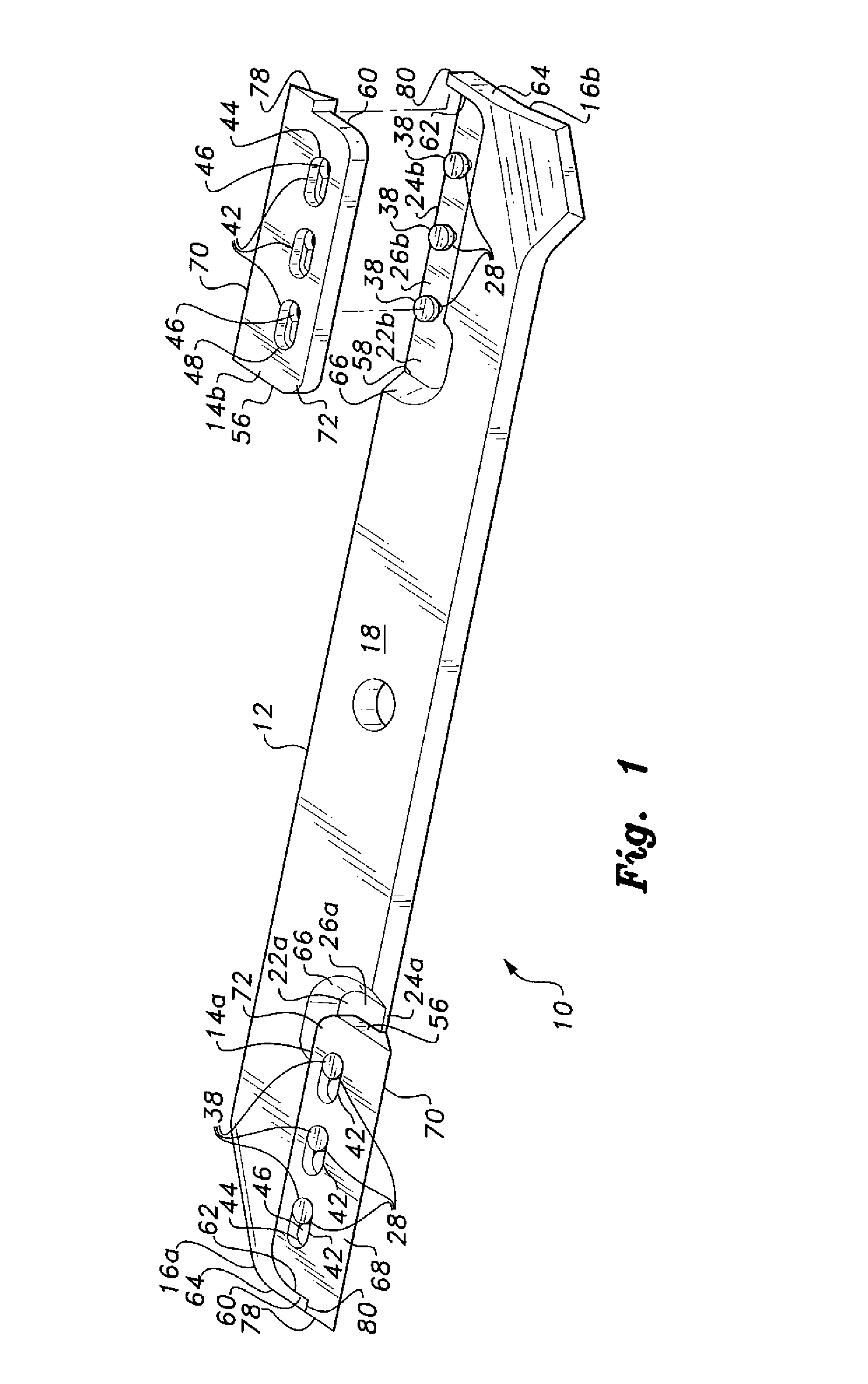
[0007]The mower blade with replaceable inserts includes a blade bar having diametrically opposite reliefs formed therein for the removable installation of cutting inserts. A plurality of headed pins extends downwardly from the floor of each relief, the pins serving to secure the cutting inserts removably to the blade bar. Each insert has a corresponding plurality of elongate slots therein, the outboard ends of the slots (the ends away from the center of rotation of the blade bar) having circular passages large enough to clear the larger heads of the retaining pins. The remainder of each slot has a narrower portion that fits closely about the narrower shank of the corresponding pin, and an outwardly stepped wider portion that fits closely about the wider head of the pin. Thus, the cutting insert may be placed over the heads of the retaining pins and slid outwardly so that the stepped portion of each slot is captured beneath the head of the corresponding retaining pin. The surfaces of the heads of the pins and the outer, downwardly facing surfaces of the corresponding cutting inserts are coplanar with one another, thus precluding (or at least greatly reducing) the capture of debris by the assembly.
[0008]The sharpened cutting edge portion of each insert has a face that extends upwardly and rearwardly (from the direction of rotation of the blade bar) to the upper surface of the blade bar. This protects the leading edge of the blade bar from damage due to impact or other causes. The replaceable cutting insert absorbs any impact damage, instead. The back of the cutting edge portion is in direct contact with the leading edge of the blade bar. This serves to transfer any impact forces directly to the blade bar, rather than through the insert attachment pins. Moreover, the extremely close fit between the cutting insert and the blade bar precludes (or at least greatly reduces) the capture of debris therebetween, thus making it far easier to remove and replace the cutting inserts and to maintain the blade bar and cutting insert assembly.

Problems solved by technology

This can be a difficult chore, as the blade bar is typically secured tightly to the shaft of the prime mover to prevent it from loosening due to engine vibration, striking an object, or other causes.
Many such assemblies require the extensive use of tools, however, thus providing little if any advantage over the conventional blade bar having integral cutting edges.
Moreover, all such assemblies with removable cutting elements or inserts have downwardly protruding fasteners or fastener heads that frequently impact the underlying surface and / or become contaminated with debris.
The removal of these fasteners is often a difficult process when they are damaged due to impact, or when debris has become compacted around the protruding fastener.
Such protruding fasteners are also prone to being ground away if the mower is used extensively along concrete curbs, raised stone walkways, and similar structures.
If the heads of such fasteners are ground away due to wear, the cutting elements are no longer held in place and will be flung from the blade bar with considerable force when the mower is in normal operation.
Obviously, this is extremely hazardous.
In addition, the typical replaceable cutting element or insert leaves the leading edge of the blade bar exposed, which often results in damage to the blade bar itself and the jamming of material between the blade bar and the cutting element or insert.
Also, the fasteners themselves often take the entire impact load when such a removable cutting element or insert strikes an object, rather than the load being transferred directly to the more durable blade bar.

Method used


Image

  • Mower blade with replaceable inserts
  • Mower blade with replaceable inserts
  • Mower blade with replaceable inserts

Examples


Embodiment Construction

[0016]The mower blade with replaceable inserts comprises a blade bar having diametrically opposed cutting inserts removably attached thereto. The inserts are quickly and easily removed as required for sharpening or exchange, and may be quickly and easily reinstalled without need to remove the blade bar from the mower.

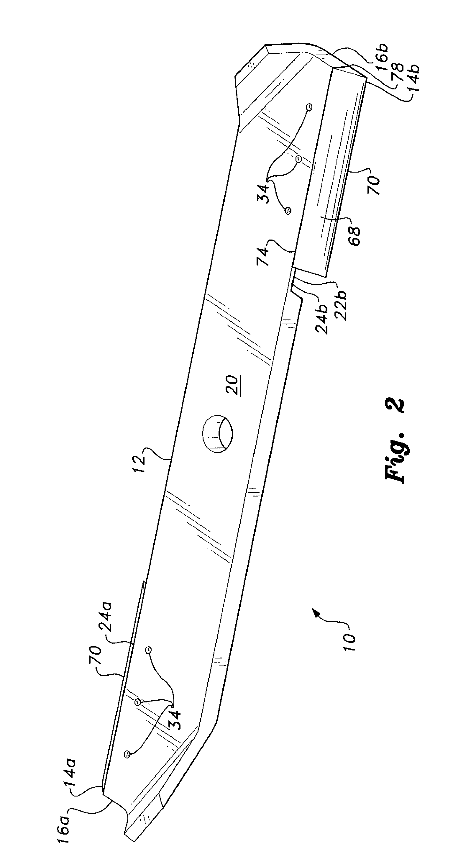
[0017]FIG. 1 of the drawings illustrates a bottom perspective view of the blade and insert assembly 10, and FIG. 2 provides a top perspective view of the assembly 10. The assembly 10 comprises a blade bar 12 having diametrically opposed, identical first and second cutting inserts 14 removably installed thereon. The second insert 14 is shown separated from the blade bar 12 in FIG. 1 to illustrate various structural details.

[0018]The blade bar 12 has identical, diametrically opposed first and second ends 16a and 16b, a lower surface 18, and an opposite upper surface 20. An insert relief 22a, 22b is formed in the lower surface 18 of the bar 12 adjacent each end 16a, 16b th...


PUM


Abstract

The mower blade with replaceable inserts includes a blade bar having diametrically opposite reliefs therein for replaceable cutting inserts. Headed pins extend from each relief, and each insert has corresponding slots. The slots have larger diameter outer ends to clear the larger diameter heads of the pins, the inner portions of the slots being stepped to fit closely about the narrower shanks of the pins. The inserts drop into position over the corresponding pins, and slide outwardly to be retained by the heads of the pins. The outer (lower) surfaces of the heads of the pins are coplanar with the outer (lower) surfaces of the inserts when installed. The cutting edge portions of the inserts extend over and are in direct contact with the corresponding leading edge portions of the blade bar, thus protecting the bar and transferring impact forces directly to the bar rather than through the pins.

Description

BACKGROUND OF THE INVENTION[0001]1. Field of the Invention[0002]The present invention relates generally to the cutting and trimming of vegetation, and particularly to a mower blade with replaceable inserts that serve as the cutting elements of the blade, and that may be removed from and replaced upon the blade bar without extensive need of tools.[0003]2. Description of the Related Art[0004]Powered rotary lawnmowers and the like conventionally have a single rotating blade bar powered by a prime mover (reciprocating internal combustion engine, electric motor, etc.). The blade bar is conventionally provided with cutting edges as integral components of the blade. When these cutting edges become dulled, it is necessary to remove the blade bar from the mower in order to sharpen the cutting edges. This can be a difficult chore, as the blade bar is typically secured tightly to the shaft of the prime mover to prevent it from loosening due to engine vibration, striking an object, or other cau...

Claims


Application Information

Patent Timeline
Patent Type & Authority Applications(United States)
IPC IPC(8): A01D34/52
CPCA01D34/73
Inventor BLAREK, JAMES A.
Owner BLAREK JAMES A
Learn More