Ultra low emissions gas turbine combustor

a gas turbine and low-emission technology, applied in the field of can combustors, can solve the problems of high carbon monoxide emissions, easy proneness of the combustion system utilizing can type combustors, and high air flow mal-distribution, and achieve the effect of preventing flow separation

Active Publication Date: 2012-05-10
OPRA TECH
View PDF12 Cites 37 Cited by
  • Summary
  • Abstract
  • Description
  • Claims
  • Application Information

AI Technical Summary

Problems solved by technology

Gas turbine combustion systems utilizing can type combustors are often prone to air flow mal-distribution.
However, the use of film cooling in these low flame temperature combustors generates high levels of carbon monoxide emissions.
External impingement cooling of the flame tube (liner) can curtail such high levels.
Moreover, in systems where high exit temperature is a performance requirement in addition to low NOx, the air flow to swirler / reaction zone is a large proportion of total air flow and therefore cooling and dilution air flows are limited.

Method used


Image

  • Ultra low emissions gas turbine combustor
  • Ultra low emissions gas turbine combustor
  • Ultra low emissions gas turbine combustor

Examples


Embodiment Construction

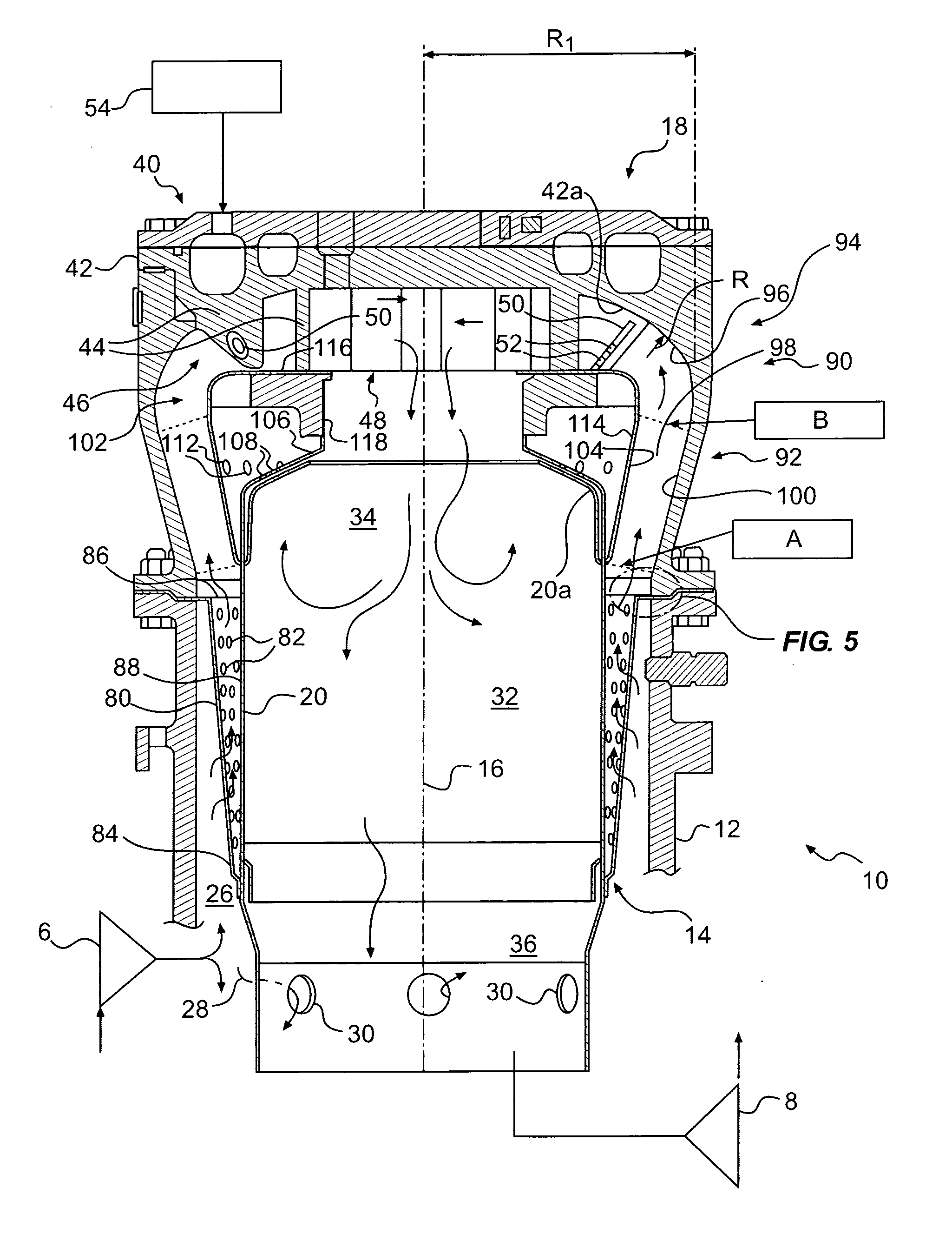
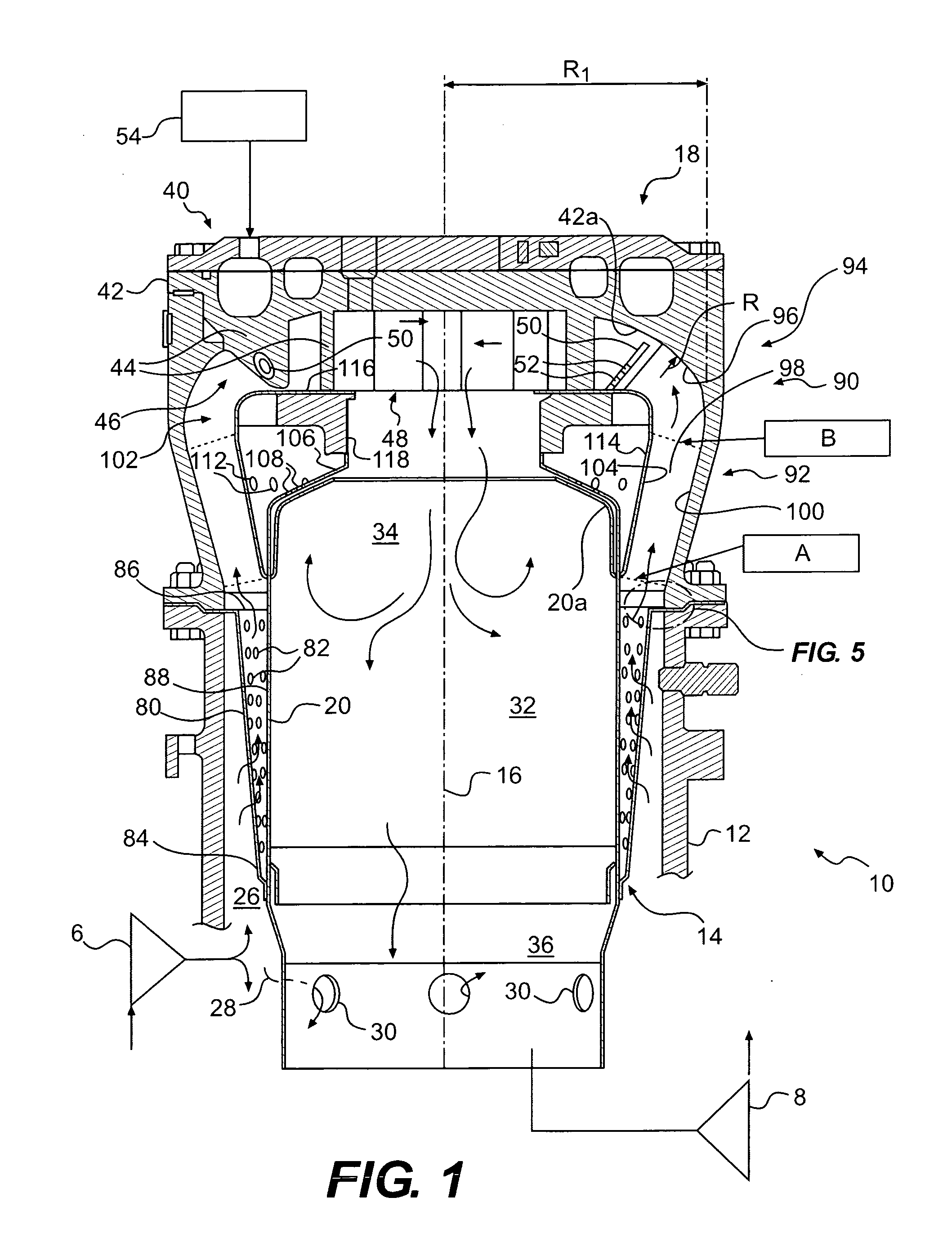
[0012]The can combustor of the present invention, generally designated by the numeral 10 in the figures, is intended for use in combusting gaseous fuel with compressed air from compressor 6, and delivering combustion gases to gas turbine 8, e.g., for work-producing expansion such as in a gas turbine engine. See FIG. 1. Compressor 6 may be a centrifugal compressor and gas turbine 8 may be a radial inflow turbine, but these are merely preferred and are not intended to limit the scope of the present invention, which is defined by the appended claims and their equivalents.

[0013]In accordance with the present invention, as embodied and broadly described herein, the can combustor may include a generally cylindrical housing having an interior, an axis, and a closed axial end. As embodied herein, and with reference to FIG. 1, can combustor 10 includes outer housing 12 having interior 14, longitudinal axis 16, and closed axial end 18. Housing 12 is generally cylindrical in shape about axis 1...


PUM


Abstract

The gaseous fuel-fired can combustor for a gas turbine include a generally cylindrical housing, and a generally cylindrical liner disposed coaxially within the housing to define with the housing a radial outer flow passage for combustion air, the-liner also defining inner combustion and a dilution zone, the dilution zone being axially distant a closed housing end relative to the combustion zone. A fuel / air mixing apparatus disposed at the closed housing end includes a plurality of swirl vanes defining passages each having constant cross-section flow areas along the vanes, and an increasing aspect ratio from the passage inlet to the outlet. An impingement cooling sleeve coaxially disposed in the combustion air passage between the housing and the liner cools the portion of the liner defining the combustion zone. Channeling apparatus is disposed between a downstream end region of the sleeve and the mixing apparatus and includes a diffuser section with a ratio of the outlet flow area to the inlet flow area in a range of 1.3-1.5.

Description

FIELD OF THE INVENTION[0001]The present invention relates to can combustors. In particular, the present invention relates to gaseous fuel-fired, impingement cooled, dry low emission can combustors for gas turbine engines.BACKGROUND OF THE INVENTION[0002]Gas turbine combustion systems utilizing can type combustors are often prone to air flow mal-distribution. The problems caused by such anomalies are of particular concern in the development of low NOx systems. The achievement of low levels of oxides of nitrogen in combustors is closely related to flame temperature and its variation through the early parts of the reaction zone. Flame temperature is a function of the effective fuel-air ratio in the reaction zone which depends on the applied fuel-air ratio and the degree of mixing achieved before the flame front. These factors are obviously influenced by the local application of fuel and associated air and the effectiveness of mixing. Uniform application of fuel typically is under contr...

Claims


Application Information

Patent Timeline
Patent Type & Authority Applications(United States)
IPC IPC(8): F23R3/42
CPCF23D2900/14021F23R3/14F23R2900/03044F23R3/286F23R3/54F23R3/16
Inventor AXELSSON, AXEL LARS-UNO EUGENBERAN, MARTINSINKEVICH, EKATERINA
Owner OPRA TECH
Why Eureka
Try Eureka