Flywheel

Inactive Publication Date: 2012-05-10
RICARDO UK LTD
View PDF6 Cites 3 Cited by
  • Summary
  • Abstract
  • Description
  • Claims
  • Application Information

AI Technical Summary

Benefits of technology

[0008]The indicator ring may be mounted to the flywheel with an interference fit, and is supported either by the support member or by the drive transfer element (for example, a shaft). The ring can be constructed from circumferentially wound fibre (for example, carbon fibre), or can be another material with sufficient strength in hoop to enable it to be rotated at the maximum designed flywheel speed without failing, and with a suitable stiffness as further described below. When mounted to the support member, the ring can be radially disposed inside or outside of the support member. When the ring is radially disposed inside of the support member, the ring has a stiffness which is greater than or substantially the same as that of the support member. When the ring is radially disposed outside of the support member, the ring has a stiffness which is lower than or substantially the same as that of the support member. The support member comprises circumferentially wound fibre, for example carbon fibre. When mounted to the drive transfer element (for example, a shaft), the ring has a stiffness which is lower than or substantially the same as that of the drive transfer element.
[000

Problems solved by technology

Because a warning or indicator ring is incorporated with the flywheel to behave differently under rotation, when the flywheel reaches undesirable rotational speeds a detector can detect consequences of the different behaviour, for example, imbalance in the flywheel.
Th

Method used


Image

  • Flywheel
  • Flywheel
  • Flywheel

Examples


Example

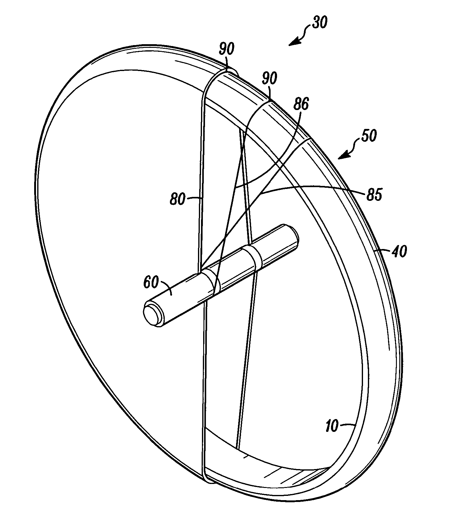
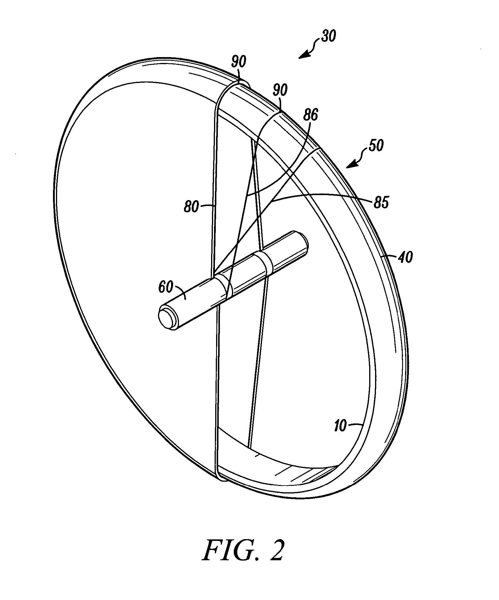
[0049]Referring to FIGS. 8 and 9, which show a first embodiment of a flywheel (30) having a warning or indicator ring (800), it can be seen that the warning ring (800) is mounted on the outer periphery of the support element (40). The warning ring (800) is mounted radially outside the support element (40), using an interference fit, and is typically pressed into place. The interference fit between the warning ring (800) and the support element (40) results in a pre-load force between these two components when the flywheel (30) is at rest. The assembly of warning ring (800) to support element (40) results in a residual non-uniform stress between the two. The winding (80) passes around the warning ring (800), support element (40) and mass element (10). The flywheel is finely balanced to avoid vibration when rotating. During manufacture, the balancing operation is performed after the warning ring is assembled such that it is balanced with the warning ring in place.

[0050]As shown in FIG...

Example

[0054]In the second embodiment shown in FIGS. 10 and 11 the warning ring passes outside the winding (80) and its relative stiffness is selected accordingly to provide the same effects.

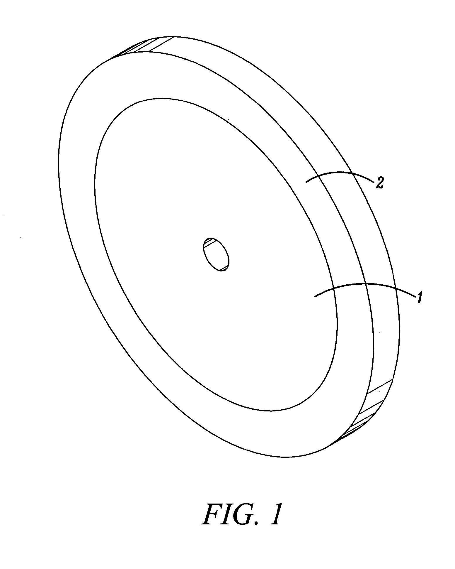
[0055]In a further embodiment, as shown in FIGS. 12 and 13, the warning ring (800) is mounted with an interference fit, radially inside the support element (40). The mass element (10) is interposed between the support element (40) and the warning ring (800) in this embodiment, but in other embodiments can be incorporated in the support element (40) as previously described or the warning ring can be interposed between the mass element (10) and support element (40). In these further embodiments the warning ring (800) has a higher Young's modulus (is stiffer) than the support element (40).

[0056]In operation when the flywheel is rotated, the support element (40) grows radially (under centrifugal forces) a greater amount than the warning ring (800) grows. Similarly to the previous embodiments, the pre-load ...


PUM

PropertyMeasurementUnit
Forceaaaaaaaaaa
Massaaaaaaaaaa
Speedaaaaaaaaaa

Abstract

The invention relates to an apparatus and method for constructing a flywheel for energy storage, the flywheel having a drive transfer element and a rim comprising a mass element, the drive transfer element being coupled to the rim by a winding around each, and the flywheel incorporating an indicator ring functioning as a mechanical fuse for providing an indication of excessive flywheel component stress.

Description

BACKGROUND OF THE INVENTION[0001]Flywheels are known for the storage of energy in the form of kinetic energy, for example for use in vehicles. In such instances it is known to use a flywheel to store the energy which would otherwise be converted to heat in the vehicle's braking system when the vehicle decelerates, this stored energy then being available for use to accelerate the vehicle when desired.[0002]An existing type of flywheel according to FIG. 1 has a central metallic support section (1) which can be mounted on a central support such as a shaft. At least one composite ring (2) is mounted on the central support section. The composite ring in this type of flywheel is filament wound from carbon fibre. When the flywheel is in rotation, the ring will tend to expand in diameter due to the centrifugal forces acting on it. The ring has high strength in hoop for re-acting the centrifugal forces when the flywheel is in rotation. However, the outer ring can become a loose fit on the ce...

Claims


Application Information

Patent Timeline
IPC IPC(8): F16C15/00B23P11/00F16F15/30
CPCF16C15/00F16F15/305Y10T74/212Y10T29/49826Y02E60/16F16C2361/55
Inventor ATKINS, ANDREW FARQUHAR
Owner RICARDO UK LTD
Why Eureka
Try Eureka