Connector for a Safety Restraint System

a safety restraint and connection technology, applied in the direction of coupling device connection, pedestrian/occupant safety arrangement, instruments, etc., can solve the problems of increasing production costs, increasing costs, and no longer being possible, and achieves reliable monitoring of the correct coupling action, the effect of cost saving and cost saving

Active Publication Date: 2012-05-10
APTIV TECH LTD
View PDF12 Cites 14 Cited by
  • Summary
  • Abstract
  • Description
  • Claims
  • Application Information

AI Technical Summary

Benefits of technology

[0013]The inventive construction of the squib connector allows to electrically monitor the correct coupling of the plug-connector with its corresponding counterpart without the necessity for a shorting clip according to the prior art. The inventive construction is further more cost-efficient than the provision of a shorting clip so that the solution of the present invention allows a cheaper construction for (squib) connectors which offers at the same time a reliable monitoring of the correct coupling action. With squib connectors of the present invention no additional or separate shorting clip is necessary for the squib (but the invention does not necessarily prevent from using an additional shorting clip).

Problems solved by technology

On the one hand, the necessary provision of the above described shorting clips leads to a significant increase in production costs, since not only a separate part has to be provided and assembled but also since the provision of a shorting clip in a retainer or airbag receptacle limits the design freedom for squib connectors thereby further increasing the costs since it is very often not possible to use the optimum design for plug-connector and retainer due to the necessary regard for the shorting clip.
Without a shorting clip, this is no longer possible with the existing connector systems so that shorting clips are still necessary for their monitoring function, although the “shorting function” itself is no longer strictly necessary.

Method used


Image

  • Connector for a Safety Restraint System
  • Connector for a Safety Restraint System
  • Connector for a Safety Restraint System

Examples


first embodiment

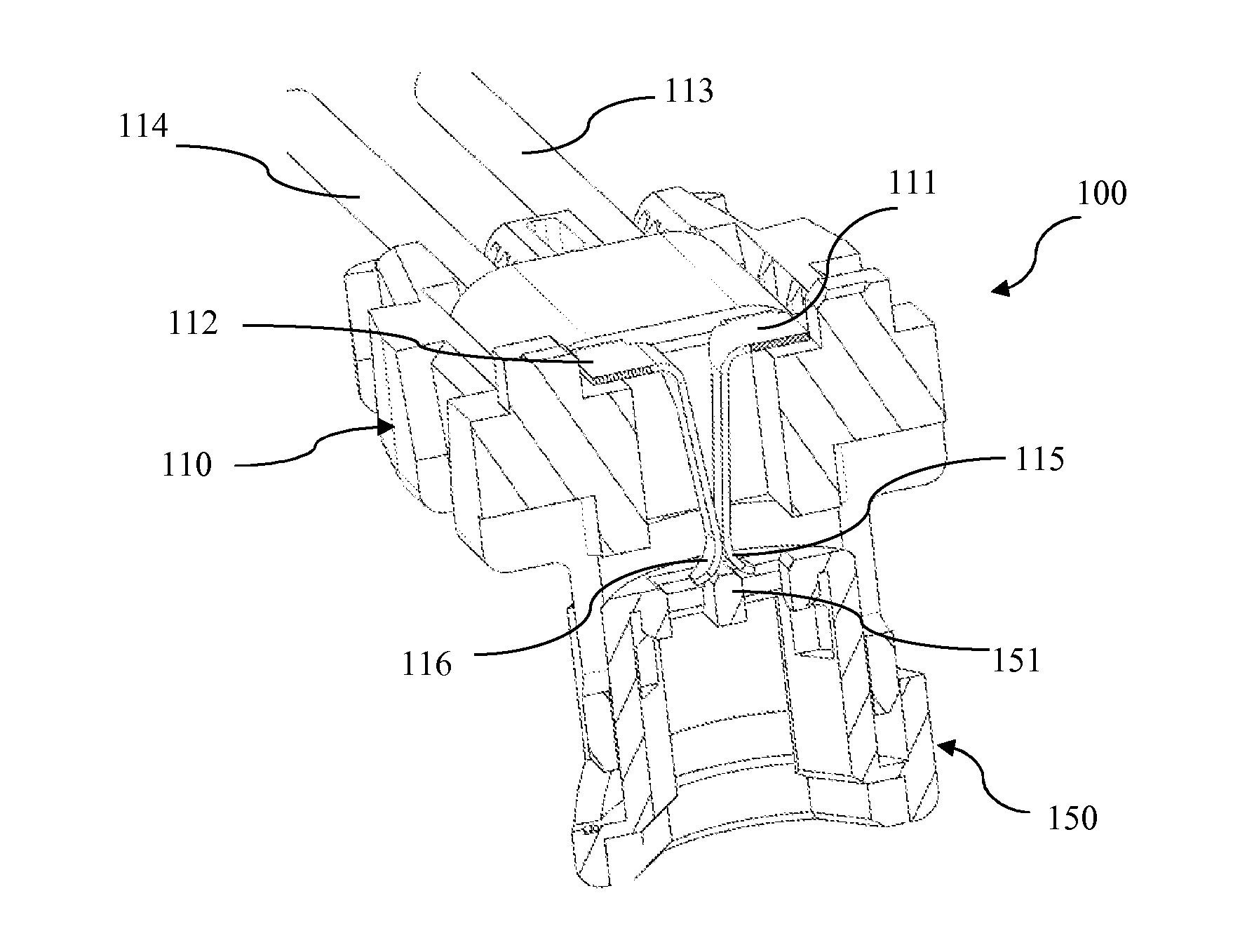
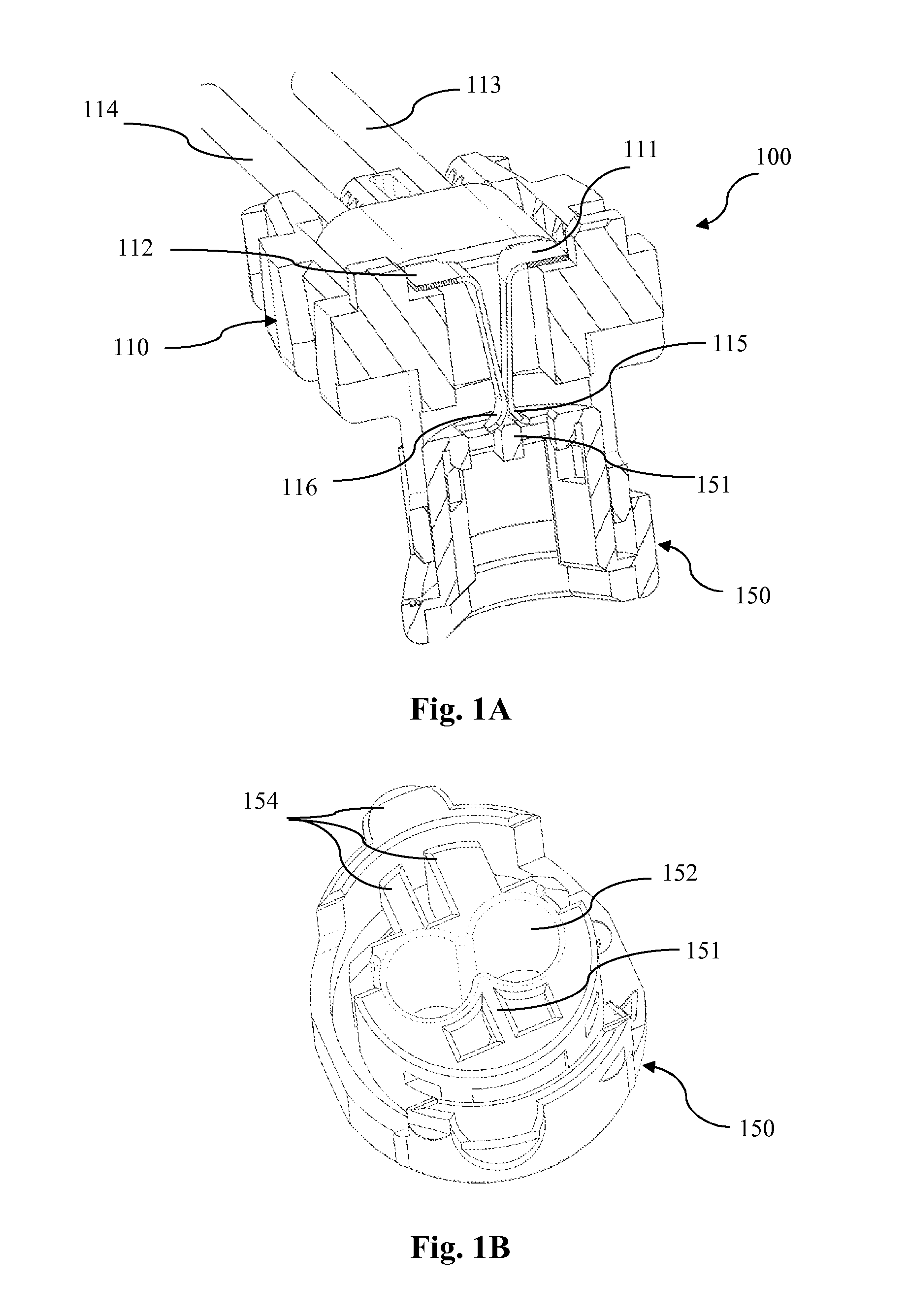
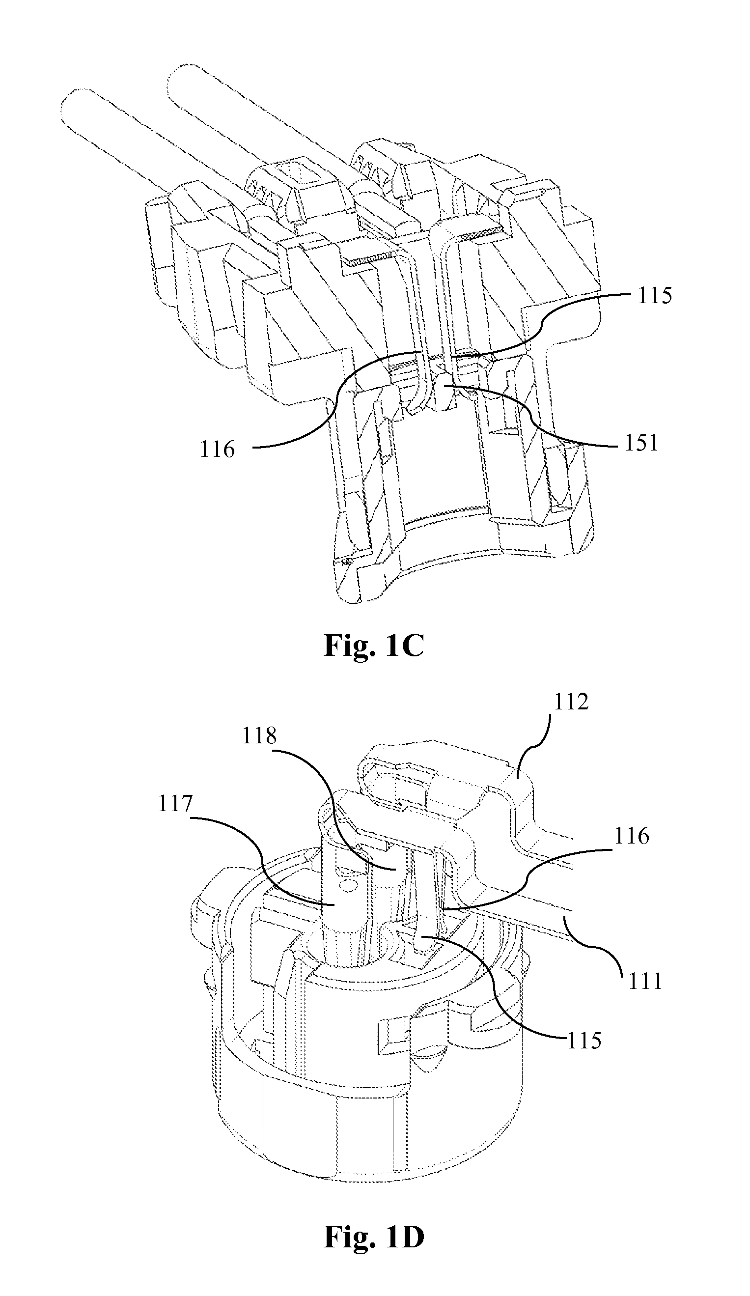
[0015]FIGS. 1A-D show schematic illustrations of a squib connector in accordance with the invention;

[0016]FIGS. 2A-D show schematic illustration of a further embodiment of the invention;

[0017]FIGS. 2E-F show an alternative arrangement of the contact means of the embodiment shown in FIGS. 1A to D;

third embodiment

[0018]FIGS. 3A-D show a third embodiment in accordance with the invention; d

[0019]FIGS. 4A-D show a forth embodiment in accordance with the invention;

[0020]FIGS. 5A-5D show a 5th embodiment in accordance with the invention; and

[0021]FIGS. 6A-D show a 6th embodiment in accordance with the invention.

[0022]Throughout the figures, like components are denoted with similar reference numbers, whereby the reference numbers are three-digit and the first digit indicates the respective figure (e.g.: reference numbers 111 and 112 are used for the terminals shown in FIGS. 1A-D and reference numbers 211 and 212 are used for the corresponding terminals shown in FIGS. 2A-D)

[0023]FIGS. 1A-D show different views of a squib connector assembly 100 comprising a plug connector 110 being provided with two terminals 111, 112 having corresponding signal lines 113, 114. In the schematic illustration of FIG. 1A the squib connector is shown in a cut view and the cover closing the housing of plug connector 110 ...


PUM


Abstract

The present invention relates to squib connectors for instance for airbag ignition systems, which allow the electrical or electronic monitoring of the correct coupling of a squib plug-connector with its corresponding counterpart. According to the invention, a squib connector has at least two terminals having corresponding signal lines. In order to allow an electrical monitoring of the correct coupling of the plug connector, the terminals are in electrical contact with each other in the uncoupled or incorrectly coupled condition of the plug connector. This electrical contact between the terminals is adapted for being separated upon correct coupling to a corresponding counter-connector either automatically or by an actuating action. The disconnecting of the terminals may then be monitored by any suitable monitoring means.

Description

1. FIELD OF THE INVENTION[0001]The invention relates to a connector for a safety restraint system (SRS), for instance to squib connectors for airbag ignition systems and in particular to plug-connectors comprising two terminals with which it is possible to electrically or electronically monitor the correct coupling of the plug-connector with a suitable counter connector.2. TECHNICAL BACKGROUND[0002]Passenger cars have nowadays a number of safety restraint systems, such as seat belt pre-tensioners or airbags, as e.g. front and side airbags, which serve to cushion or limit the impact of a passenger with for example interior parts of passenger cars in case of an accident. Deceleration sensors in the passenger vehicle detect high deceleration values as they occur in case of an accident and send a trigger signal via a wire or cable to SRS devices. An explosive device, known as a squib, inflates the airbag or tightens the belt. The wires or cables from the deceleration sensor are connecte...

Claims


Application Information

Patent Timeline
Patent Type & Authority Applications(United States)
IPC IPC(8): G01R31/04
CPCF42B3/26H01R13/7033H01R13/641F42C19/06B60R21/264B60R2021/26035
Inventor ODORFER, FRANKREGNIER, VINCENTKUEHNEL, BERHARDGUNREBEN, MICHAEL
Owner APTIV TECH LTD
Why Eureka
Try Eureka