

Radar device
a technology of a radar and a radar plate, which is applied in the direction of measurement devices, multi-channel direction-finding systems using radio waves, instruments, etc., can solve the problems of insufficient number and difficulty in estimating angles based on the conventional esprit method, and achieve the effect of suppressing processing tim
- Summary
- Abstract
- Description
- Claims
- Application Information
AI Technical Summary
Benefits of technology
Problems solved by technology
Method used
Image

Examples
embodiment 1
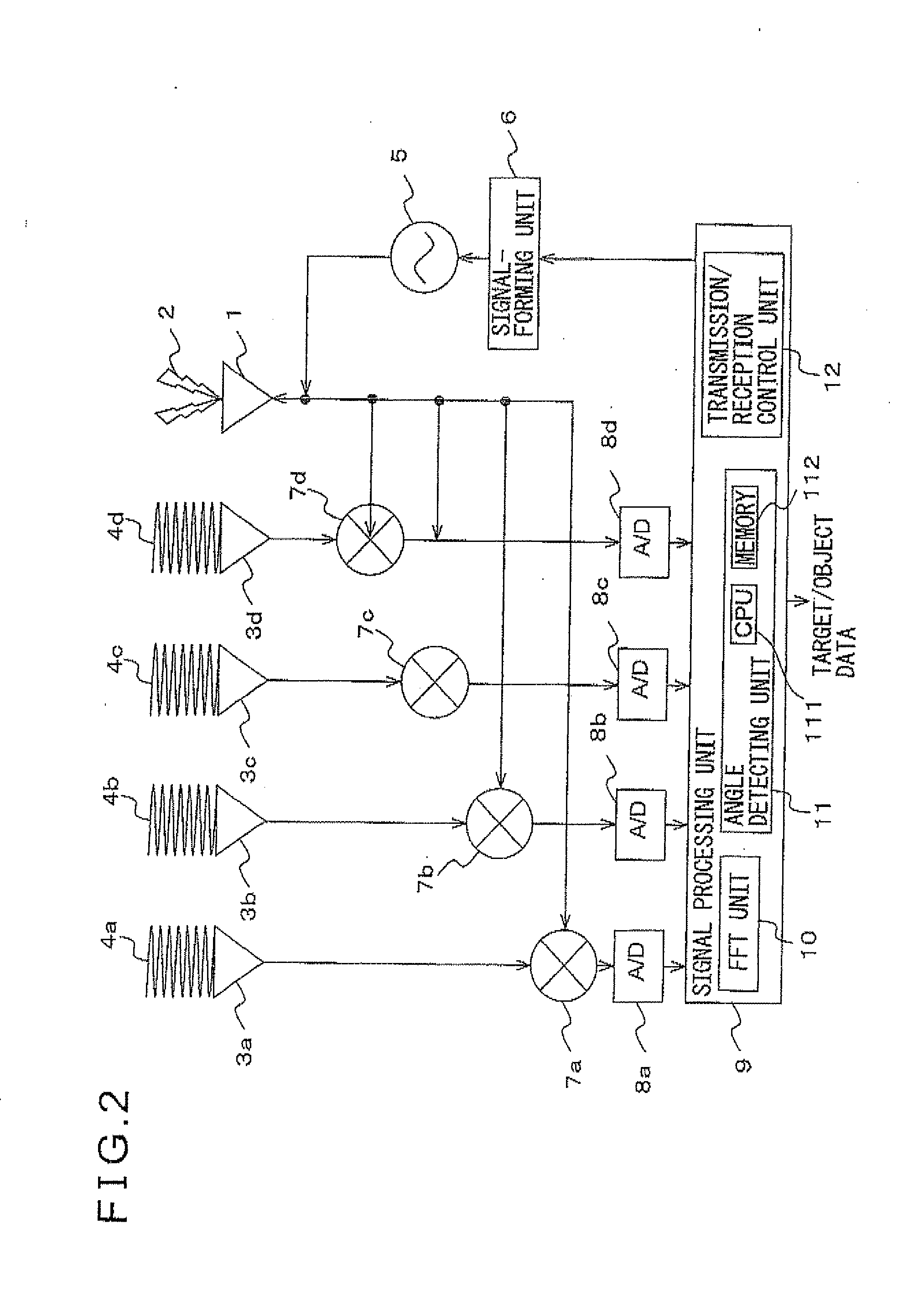
[0041]First, a radar device according to an embodiment 1 of the present invention will be described with reference to the drawings. FIG. 2 is a diagram illustrating the constitution of the radar device according to the embodiment 1 of the invention. A signal-forming unit 6 is controlled by a transmission / reception control unit 12 in a signal processing unit 9, and desired modulation signals are output from the signal-forming unit 6. An oscillator 5 feeds transmission signals which are modulated based on the modulation signals, and electromagnetic waves 2 are transmitted from a transmission antenna 1. The transmission signals are reflected from an object or a target (not shown) and are received as reflected waves 4a to 4d by reception antennas 3a to 3d. The reception signals are mixed by mixers 7a to 7d with the transmission signals. Thereafter, the reception signals are converted into digital signals through A / D converters 8a to 8d, fed to the signal processing unit 9, processed by ...
embodiment 2
[0076]Next, the radar device according to an embodiment 2 of the invention will be described with reference to the drawings. FIG. 7 illustrates the constitution of the angle detecting unit in the radar device according to the embodiment 2 of the invention. The constitution of the radar device of the embodiment 2 in other respects is the same as that of the embodiment 1, and is not described in detail.
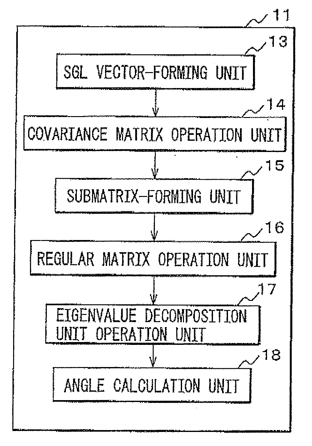
[0077]The radar device of the present invention has a feature in the constitution of the angle detecting unit 11. What makes a difference from the angle detecting unit in the radar device of the embodiment 1 is that a column vector-forming unit 19 is provided instead of the covariance matrix operation unit 14.
[0078]Next, described below is the method of calculating the angle in the radar device according to the embodiment 2 of the invention. FIG. 8 is a flowchart illustrating the procedure of calculating the angles according to the embodiment 2 of the invention. In the invention, the da...
embodiment 3
[0084]Next, the radar device according to an embodiment 3 of the invention will be described with reference to the drawings. FIG. 9 illustrates the constitution of the angle detecting unit in the radar device according to the embodiment 3 of the invention. The constitution of the radar device of the embodiment 3 in other respects is the same as that of the embodiment 1, and is not described in detail.
[0085]The radar device of the present invention has a feature in the constitution of the angle detecting unit 11. What makes a difference from the angle detecting unit in the radar device of the embodiment 1 is that a partial vector operation unit 20 is provided instead of the covariance matrix operation unit 14, an evaluation function-forming unit 21 is provided instead of the regular matrix operation unit 16, and a minimum value calculation unit 22 is provided instead of the eigenvalue decomposition unit 17.
[0086]Next, described below is the method of calculating the angle in the rada...
PUM
 Abstract
Description
Claims
Application Information